


9
ROUTINE MAINTENANCE AND CARE
FOR THE EQUIPMENT OWNER
Before proceeding with those things you might want to maintain
yourself, please carefully consider the following:
FIRE, EXPLOSION HAZARD
Failure to follow this warning could result in personal injury,
death, and/or property damage.
1.Turn off gas supply and electrical power to your unit before
servicing or performing maintenance.
2. Do not turn off electrical power to this unit without first
turning off gas supply and apply lockout tags.
3. When removing access doors or performing maintenance
functions inside your unit, be aware of sharp sheet metal
parts and screws. Although special care has been taken to
reduce sharp edges to a minimum, be extremely careful
when handling parts or reaching into the unit.
!
WARNING
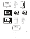
Air Filter(s)
Air filters should be checked at least every 3 or 4 weeks and
changed or cleaned whenever they become dirty. Table 1 indicates
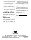
the correct filter size for your unit. Open the filter access panel to
replace or inspect the filters. All units have filter tracks into which
the filters slide. Remove the filters by pulling the filter slide
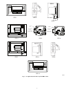
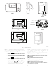
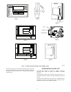
outward from the track. See Fig. 6 for filter access panel location.
Note the direction of flow arrows on the filter frame.
If you have difficulty in locating your air filter in the return--air
duct system, or if you have questions concerning proper filter
maintenance, contact your dealer for instructions. When replacing
your unit filters, always use the same size and type of filter that was
originally supplied by the installer. Filter tracks are field
convertible for 2 or 4--in. thick filters. Verify airflow and duct
static values and related motor sizing and belt drive adjustment, if
filter type or efficiency rating is changed from the original
installation.
Units with outdoor air capability have cleanable filters for the
outdoor air. These filters should be checked quarterly and cleaned
as necessary. Remove by pulling out the middle of the hood top.
Push up on the center filter and then remove. Slide the other filters
to the center and repeat.
FIRE AND EQUIPMENT DAMAGE HAZARD
Failure to follow this warning could result in personal injury,
death, and/or property damage.
Never operate unit without filters in place. Damage to blower
motor and/or compressors could result. An accumulation of
dust and lint on internal parts of your unit can cause loss of
efficiency and in some cases, fire.
!
WARNING
Table 1 – Indoor Air Filter Data
UNIT
48HG,HJ,
PG, PM
TYPE OF FILTER
QUANTITY...SIZE
(in.)
014---024
and 16 --- 24
Standard Throwaway, Optional
30%, or Accessory 65% Pleated
9...16 x 25 x 2
028 and 28
Standard Throwaway, Optional
30%, or Accessory 65% Pleated
9...20 x 25 x 2
PULL OUT CENTER OF
HOOD TO RELEASE OUTDOOR AIR
FILTER FROM TRACK
CONTROL BOX
ACCESS DOOR
INDOOR MOTOR
ACCESS DOOR
GAS VALVE
CONNECTION
FILTER
ACCESS
DOOR
HEAT
SECTION
ACCESS
PANEL
C07352
Fig. 6 -- Panel and Filter Locations
Alarm Status
(Units with ComfortLinkt Controls)
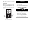
The Scrolling Marquee display incorporates an Alarm Status LED
that turns on to indicate an active alarm or alert. These alarms and
alerts are in addition to those that are indicated by the Integrated
Gas Control (IGC). The ComfortLink control active alarm codes
and alarm history can be viewed with the Scrolling Marquee or
other Carrier Comfort Networkr (CCN) devices. Alarms may also
be configured to broadcast automatically on CCN. If the unit will
not operate and the Alarm Status LED is on, contact the local
dealer and request service.
Integrated Gas Controller (IGC)
The IGC board incorporates an LED that emits a flashing light to
indicate an alarm code. If the furnace section will not operate and
the LED is flashing a code (1 to 9 flashes in succession), contact
your dealer and request service. (See Fig. 1.)
NOTE: Make note of the flash code before powering off the unit.
The alarm codes clear after power cycle.