


2
ELECTRICAL SHOCK HAZARD
Failure to follow this warning could result in personal injury
or death.
Before performing recommended maintenance, be sure main
power switch to unit is turned off and lockout tag is installed.
!
WARNING
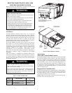
Your combination heating/cooling unit is equipped with direct
spark ignition and induced draft power combustion blower.
FIRE, EXPLOSION HAZARD
Failure to follow this warning could result in personal injury,
death and/or property damage.
Burners will light automatically. Do not attempt to light by
hand.
!
WARNING
ELECTRICAL OPERATION HAZARD
Failure to follow this warning could result in personal injury,
death, or property damage.
Do not use this unit if any part has been under water. A
flood--damaged unit is extremely dangerous. Attempts to use
the unit can result in fire or explosion. A qualified service
agency should be contacted to inspect the unit and to replace
all gas controls, control system parts, electrical parts that have
been wet or the furnace if deemed necessary.
!
WARNING
IMPORTANT: Always keep the unit’s area clear of combustible
materials. Do not obstruct the air openings to the unit. Air is
required for combustion and ventilation proper operation. Follow
the instructions provided in this book for lighting and shutting
down the unit. Should the gas supply fail to shut off or if
overheating occurs, shut off the gas valve to the unit before
shutting off the electrical supply. The following inspections must
be completed post unit installation. The detailed routine
maintenance inspections are in the Maintaining Your Unit section.
Post Unit Installation Inspection:
1. All flue and vent connections are clear and free of obstruc-
tions, are leak--free and not damaged.
2. Duct connections are leak--free and physically sound.
3. The unit base support is free of cracks, gaps, etc.
4. There are no signs of unit deterioration.
5. Burners are aligned correctly.
6. Follow routine maintenance inspection.
DETERMINE TYPE OF UNIT CONTROL
The procedures used to light or shut off the unit depend on the type
of unit control. This section will help determine the control type of
the unit.
Electro--Mechanical Control
These units may be controlled directly by a thermostat, or
indirectly by a third--party control that connects to the thermostat
inputs. For direct thermostat control, use the Electro--Mechanical
Control procedures in this book. For units with third--party
controls connected to the thermostat inputs, refer to the third--party
control instructions for procedures to ensure complete unit shut off.
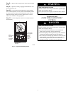
ComfortLinkt Control
These units have a factory--installed Carrier ComfortLink control.
A Scrolling Marquee display is located on the front of the unit
control box behind the control box and compressor access door.
These units may be controlled directly by a thermostat, directly by
a space temperature sensor, or indirectly through other Carrier
Comfort Networkr (CCN) communication devices. To ensure
complete unit shut off, use the ComfortLink Control procedures in
this book.
TO LIGHT UNIT
(UNITS WITH THERMOSTAT CONTROL)
FIRE, EXPLOSION HAZARD
Failure to follow this warning could result in personal injury
or death.
1. Do not turn off the electrical power to unit without first
turning off the gas supply and apply lockout tags.
2. Before attempting to start the gas heating section, familiarize
yourself with all the procedures that must be followed.
3. Never attempt to manually light the burners on the unit with
a match, lighter, or any other flame. If the electric sparking
device fails to light the burners, refer to the shutdown
procedures, then call your dealer as soon as possible.
!
DANGER
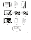
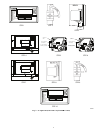
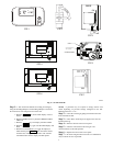
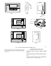
See Fig. 1 for location of gas valve. Refer to Fig. 2 while
proceeding with the following steps.
Step 1 — Set room thermostat to the lowest temperature setting
andsetSYSTEMswitchtoOFFposition.
Step 2 — Close the external gas pipings manual shut off valve
located outside the unit.
Step 3 — Turn off the electrical supply to the unit and
install lockout tag.
Step 4 — Remove the heat section access panel.
Step 5 — Turn the Off/On selector switch on the gas valve to
the OFF position and wait 5 minutes.
Step 6 — Move the Off/On selector switch on the gas valve to
the ON position.
Step 7 — Replace the heat section access panel.