


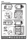

42 GW
GB - 12
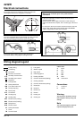
IMPORTANT for units with electric heaters;
The unit is equipped with two thermostats: one with automatic
reset and one with manual (electric) reset that can be
reactivated by switching the power supply off and then on.
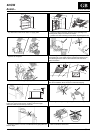
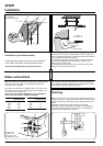
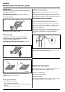
Connect the power cables to terminal box connectors in
accordance with the wiring diagram and tighten firmly.
IMPORTANT:
• Make ground connection prior to any other electrical
connections.
• If the unit is fitted with an electric heater, this must have a
separate power supply.
Ensure that the mains supply connection is made through a
switch that disconnects all poles, with a contact gap of at least 3
mm.
• Fix the power cable of the electric resistance heaters under the
single cable clamp. Make certain that the YELLOW/GREEN
cable is stripped back further than the others.
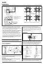
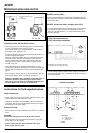
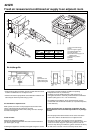
The control panel can be reached by opening the grille and
removing the metal covers using the 3 or 4 screws.
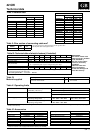
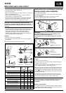
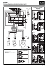
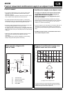
Wiring diagram legend
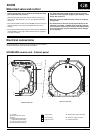
Electrical connections
ቢ Low speed
ባ Medium speed
ቤ High speed
ብ Power supply line
ቦ Heating selection
ቧ Common thermostat (heating)
ቨ Cooling selection
ቩ Common thermostat (cooling)
ቪ Neutral fan
ቫ Neutral in
ቭ Neutral out
ቮ Neutral
ቯ Heating out
ተ Cooling out
Factory wiring
Field wiring
Connector
Terminal on terminals
Normally closed contact
Normally open contact
Capacitor
FC Fan capacitor
FS Safety switch float
IFM Fan motor indoor unit
PR Drain pump relay
PS Drain pump
C1-3 Connectors
HR Heating relay
CR Cooling relay
CEV Electric valve (cooling)
HEV Electric valve (heating)
PCB Relay board
HTR Electric heater
ST Safety thermostat
T Timer
TB Terminal board
Connections
L Line phase
N Neutral
Warning:
Any warranty is declined in case of
field changes of factory wiring and
settings
Note
The connection sequence does not
represent the physical lay-out.
Cables colour
A Brown
B Blue
C Black
G Grey
R Red
W White
Y-G Yellow/Green