


GB - 11
42 GW
ENGLISH
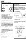
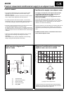
Motorized valve and control
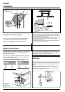
• If these connections are not made as described the drain
pan condensate may overflow.
• Valves should only open when the fan motor is working, i.e.
when one of TB1 terminals 1 or 2 or 3 is supplied from TB1
terminal 4.
• The optional electric heater (mod. 42GWE) which can only be
factory installed, must only be energized when the fan is
working.
• The optional electric heater which must be factory installed on
model 42GWE, works only if TB1 terminals 5-6 are supplied
from TB1 terminal 4.
• The water discharge pump should work every time the
cold water valve is opened, supplying TB1 terminal 7 and
8 from TB1 terminal 4.
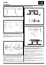
• When the system is filled with water, verify all couplings
for tightness.
• The manufacturer does not accept responsibility for the
tightness of the field - installed valve assembly and this
is not tested in the factory. He declines any responsibility
for non functioning of these assemblies and for damage
due to dripping.
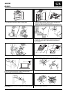
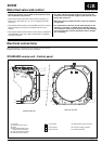
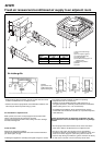
Electrical connections
ቢ Capacitor
ባ Ground connection screw
ቤ Board
ብ Relay board E-HTR (only on
models with electric heater)
ቦ Holes for panel fixing screws
ቧ Auxiliary board (accessory)
ቢ
ባ
ቤ
ብ
ቦ
C
B
A
CV
CG
CP
ቧ
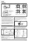
STANDARD version unit - Control panel
CV
CG CP
ቤ
ባ
C
ቢ
ቦ
ብ
A
B
ቧ
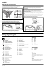
A. Electric heater supply connection
B. Unit power supply connection
C. Polarised connector
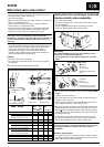
mod. 004 - 008 - 010
mod. 012 - 016 - 020
CV
CG
CP
Fan connector
Float connector
Pump connector
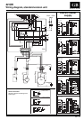
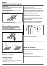
We recommend to remove the main board from the electric
panelboard for better access to electric connections.