


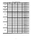
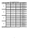
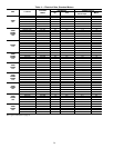
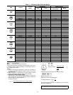
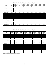
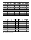
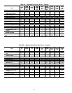
Table 5 — Electrical Data, Alternate Motors
UNIT V*-PH-HZ
VOLTAGE
LIMITS
FAN MOTOR POWER SUPPLY
Hp FLA
Minimum
Circuit Amps
MOCP
40RM
007
208/230-1-60 187-253 2.4 11.0 13.8 20
208/230-3-60 187-253 2.9 7.5 9.4 15
460-3-60 414-528 2.9 3.4 4.3 15
575-3-60 518-632 2.0 2.4 3.0 15
40RM
40RMQ
40RMS
008
208/230-3-60 187-253 2.9 7.5 9.4 15
460-3-60 414-528 2.9 3.4 4.3 15
575-3-60 518-632 3.0 3.8 4.8 15
230-3-50 207-253 2.9 7.5 9.4 15
400-3-50 360-440 2.9 3.4 4.3 15
40RMS
010
208/230-3-60 187-253 2.9 7.5 9.4 15
460-3-60 414-528 2.9 3.4 4.3 15
575-3-60 518-632 3.0 3.8 4.8 15
230-3-50 207-253 2.9 7.5 9.4 15
400-3-50 360-440 2.9 3.4 4.3 15
40RM
40RMQ
40RMS
012
208/230-3-60 187-253 3.7 10.6 13.3 20
460-3-60 414-528 3.7 4.8 6.0 15
575-3-60 518-632 3.0 3.8 4.8 15
230-3-50 207-253 5.0 14.4 18.0 30
400-3-50 360-440 5.0 7.2 9.0 15
40RM
40RMS
014
208/230-3-60 187-253 3.7 10.6 13.3 20
460-3-60 414-528 3.7 4.8 6.0 15
575-3-60 518-632 5.0 5.6 7.0 15
230-3-50 207-253 5.0 14.4 18.0 30
400-3-50 360-440 5.0 7.2 9.0 15
40RM
40RMQ
40RMS
016
208/230-3-60 187-253 5.0 15.2/14.4 19.9/18.0 30/30
460-3-60 414-528 5.0 7.2 9.0 15
575-3-60 518-632 5.0 5.6 7.0 15
230-3-50 207-253 5.0 14.4 18.0 30
400-3-50 360-440 5.0 7.2 9.0 15
40RM
40RMS
024
208/230-3-60 187-253 7.5 22.0/21.0 27.5/26.3 45/45
460-3-60 414-528 7.5 10.5 13.1 20
575-3-60 518-632 7.5 7.6 9.5 15
230-3-50 207-253 7.5 21.0 26.3 45
400-3-50 360-440 7.5 10.5 13.1 20
40RM
40RMS
028
208/230-3-60 187-253 10.0 26.4/25.0 33.0/31.3 55/55
460-3-60 414-528 10.0 12.5 15.6 25
575-3-60 518-632 10.0 9.6 12.0 20
230-3-50 207-253 10.0 25.0 31.3 55
400-3-50 360-440 10.0 12.5 15.6 25
LEGEND
FLA — Full Load Amps
MOCP — Maximum Overcurrent Protection
*Motors are designed for satisfactory operation within 10% of nomi-
nal voltages shown. Voltages should not exceed the limits shown in
the Voltage Limits column.
NOTES:
1. Minimum Circuit Amp and MOCP values are calculated in
accordance with NEC (National Electrical Code) (U.S.A. stand-
ard), Article 440.
2. Motor FLA values are established in accordance with UL (Under-
writers’ Laboratories) Standard 1995 (U.S.A. standard).
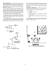
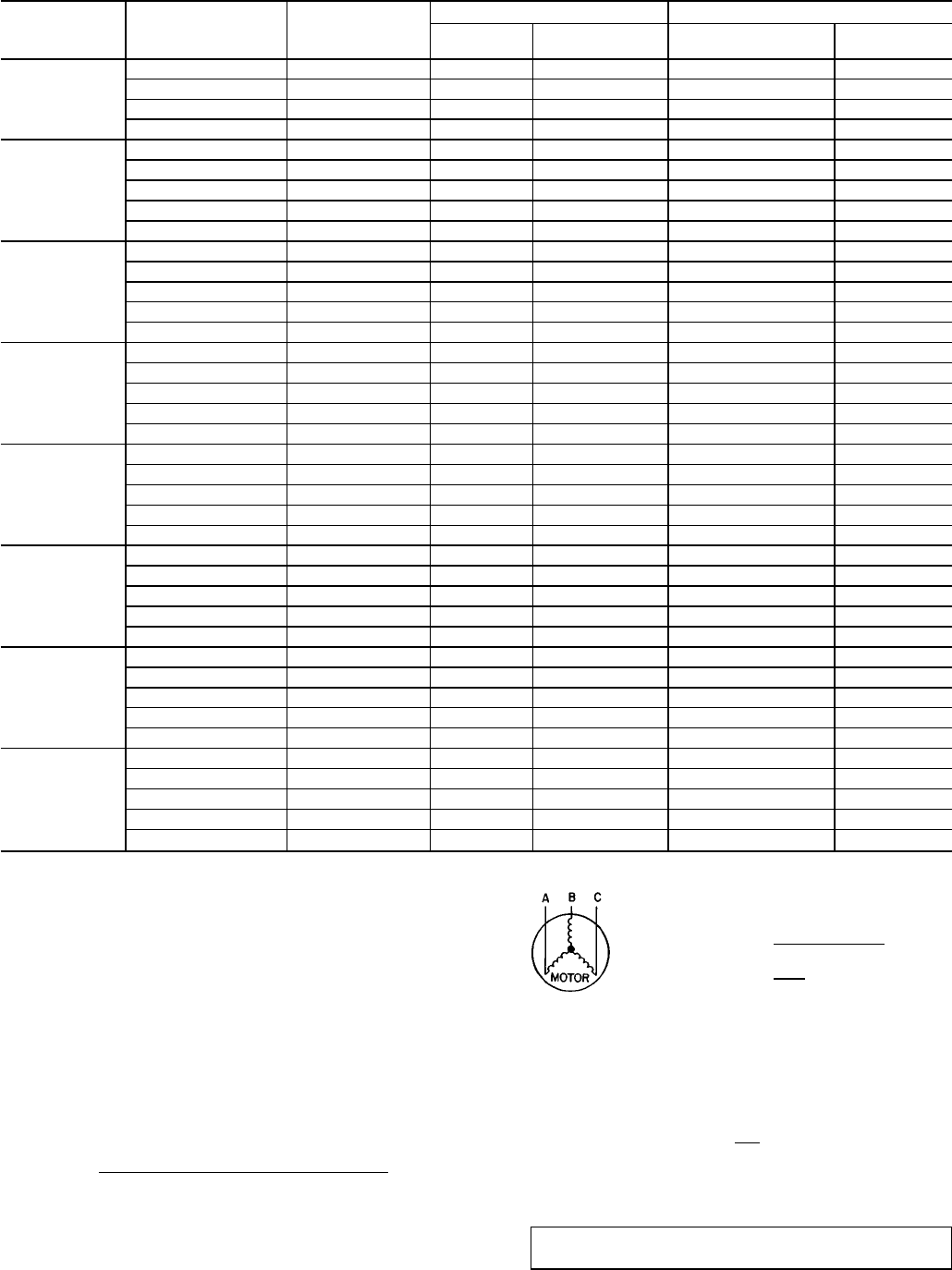
3. Unbalanced 3-Phase Supply Voltage
Never operate a motor where a phase imbalance in supply volt-
age is greater than 2%.
Use the following formula to determine
the percentage of voltage imbalance.
% Voltage Imbalance
max voltage deviation from average voltage
= 100 x
average voltage
EXAMPLE: Supply voltage is 400-3-50.
AB = 393 v
BC = 403 v
AC = 396 v
393 + 403 + 396
Average Voltage =
3
1192
=
3
= 397
Determine maximum deviation from average voltage.
(AB) 397 − 393 = 4 v
(BC) 403 − 397 = 6 v
(AC) 397 − 396 = 1 v
Maximum deviation is 6 v.
Determine percent voltage imbalance.
6
% Voltage Imbalance = 100 x
397
= 1.5%
This amount of phase imbalance is satisfactory as it is below the
maximum allowable 2%.
IMPORTANT: If the supply voltagephase imbalance is more than
2%, contact your local electric utility company immediately.
21