


IMPORTANT: Never attach the sensor to the suction
manifold. Do NOT mount the sensor on a trapped por-
tion of the suction line.
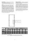
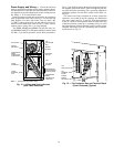
40RM Series evaporator coils have a face-split design. En-
sure that lower circuit of coil is first on/last off when con-
nected to the condensing unit and/or system controls. See
Fig. 6.
External TXV equalizer connections are provided and factory-
brazed into the coil suction manifolds.
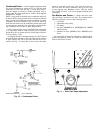
If suction line must be horizontal, clamp bulb to suction
line at least 45 degrees above bottom, at approximately the
4 o’clock or 8 o’clock position. See Fig. 7.
NOTE: The 40RMQ units are supplied with factory-installed
thermostatic expansion valves and check valve bypasses.
No extra piping connections or kits are required to install the
40RMQ with a 38AQS condensing unit in a heat pump
system, however, some field supplied components may be
required. See the following two sections.
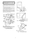
FIRST ON/LAST OFF=B
VERTICAL INSTALLATION
FIRST ON/LAST OFF=A
HORIZONTAL INSTALLATION
Fig.6—Typical Evaporator Coil Connections
(40RM, 40RMQ)
LEGEND
TXV — Thermostatic Expansion Valve
NOTE: The 8 o’clock position is shown above.
Fig. 7 — TXV Sensing Bulb Location
LEGEND
TXV — Thermostatic Expansion Valve
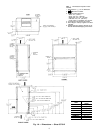
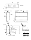
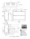
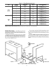
NOTE: Component location arrangement shown for field installation
of sight glasses, solenoid valves, filter driers, andTXV sensing bulbs.
The TXVs and equalizer lines are factory installed.
Fig. 5 — Face-Split Coil Suction and
Liquid Line Piping (Typical)
13