


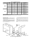

Unit Isolation — Where extremely quiet operation is
essential, install isolators between floor and base of unit, or
between ceiling and top section of unit.
Be sure that unit is level and adequately supported. Use
channels at front and sides of unit for reference points when
leveling.
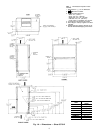
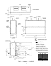
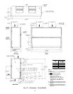
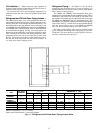
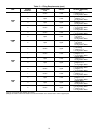
Refrigerant and Chilled Water Piping Access —
The 40RM Series units come with standard knockouts for
refrigerant and chilled water piping. These knockouts are lo-
cated on both sides of the unit for installation flexibility. The
standard knockouts provide sufficient access to the unit’s coils
for all 40RM and some 40RMQ units, however, for 40RMQ016
and 40RMS units, additional holes must be field-fabricated
to accommodate the piping. See Fig. 4 for the positions and
dimensions of the additional access holes required for these
units, including hole diameters and drilling dimensions. Rec-
ommended access hole use is also listed for all units. Note
that Fig. 4 shows the access holes on the control-box side of
the unit; this is the side of the unit with the coil headers, so
it is used most often for piping access.
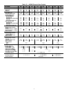
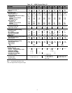
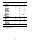
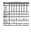
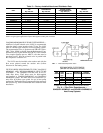
Refrigerant Piping — See Tables 1A, 1B, 1D, 1E for
refrigerant pipe connection sizes. For ease in brazing, it is
recommended that all internal solder joints be made before
unit is placed in final position.
The 40RM and 40RMQ direct-expansion units have
internal factory-installed thermostatic expansion valves (TXVs),
distributors, and nozzles for use with R-22. See Table 2 for
part numbers. Knockouts are provided in the unit corner posts
for 40RM and 40RMQ008 and 012 refrigerant piping. The
40RMQ016 unit requires additional field-fabricated piping
access holes. See Fig. 4, which also lists recommended knock-
outs and access holes to use for each 40RM and 40RMQ
unit size. Recommended fittings are listed in Table 3.
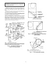
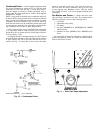
The sensor bulb capillary tubes must be routed from the
TXVs inside the unit through one of the piping access holes.
Clamp the TXV sensor bulb on a vertical portion of the suc-
tion line, outside the unit. See Fig. 5.
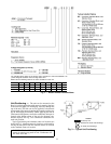
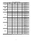
UNIT
USE HOLE
NUMBERS
FIELD-FABRICATED HOLE DIAMETERS,
in. (mm)
FIELD-FABRICATED HOLE POSITION
DIMENSIONS, in. (mm)
No. 5 No. 6 No. 7 No. 8 A B C D
40RM007,008
40RMQ008
1,3———— — — — —
40RM012-034
40RMQ012
1,2,3,4———— — — — —
40RMS008-012 4, 5 1
3
⁄
4
(44.5) — — — 6.25 (158.8) — — —
40RMS014-024 4, 5, 6, 7 1
3
⁄
4
(44.5) 1
3
⁄
4
(44.5) 1
3
⁄
4
(44.5) — 3.0 (76.2) 6.0 (152.4) 10.5 (266.7) —
40RMQ016 3*, 5, 6, 7 1
1
⁄
8
(28.6) 1
1
⁄
8
(28.6) 1
3
⁄
4
(44.5) — 3.25 (82.6) 6.125 (155.6) 10.38 (263.7) —
40RMS028,034 5, 6, 7, 8 2
1
⁄
2
(63.5) 2
1
⁄
2
(63.5) 2
1
⁄
2
(63.5) 2
1
⁄
2
(63.5) 6.0 (152.4) 9.625 (244.5) 13.38 (339.9) 17.0 (431.8)
*Must be enlarged from 1
1
⁄
8
in. to 1
3
⁄
4
inches.
NOTE: Access hole knockouts 1-4 are factory-supplied.
Fig. 4 — Refrigerant and Chilled Water Piping Access Holes
12