


7
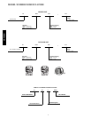
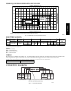
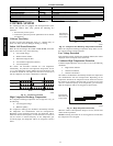
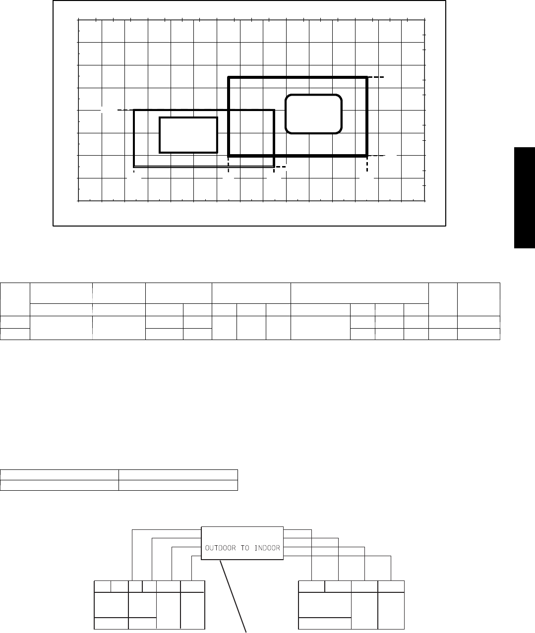
38/40GXQ SYSTEM OPERATING ENVELOPE
40
50
60
70
80
90
100
110
120
---10 0 10 20 30 40 50 60 70 80 90 100 110 120 130 140
0
5
10
15
20
25
30
35
40
45
50
55
60
--- 40 --- 35 --- 30 --- 25 --- 20 --- 15 --- 10 --- 5 0 5 10 15 20 25 30 35 40 45 50 55 60
Cooling
Continuous
Operation
Heating
Continuous
Operation
95_F
60_F
55_F
75_F
55_F
14_F
80_F
115_F
Outdoor Temperature (_C)
Indoor Temperature (_C)
Indoor Temperature (_F)
Outdoor Temperature (_F)
NOTE: Low ambient controls cannot be used with these systems
A09247
Fig. 6 – 38/40GXQ System Operating Envelope
ELECTRICAL DATA
UNIT
SIZE
SYSTEM
VOLTAGE
OPERATING
VOLTAGE*
COMPRESSOR OUTDOOR FAN INDOOR FAN{
MCA
MAX
FUSE/CB
AMP
VOLTS ---PH --- HZ MAX/MIN RLA LRA FL A HP W VOLTS FLA HP W
009
115 ---1 ---60 127/104
4.0 33
.6 .04 30 115
.3 .027 30 20 25
012 4.0 33 .45 .027 20 20 25
* Permissible limits of the voltage range at which the unit will operate satisfactorily
{ Indoor fan powered from outdoor unit.
LEGEND
FLA --- Full Load Amps
LRA --- Locked Rotor Amps
MCA --- Minimum Circuit Amps
RLA --- RatedLoadAmps
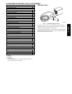
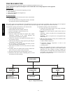
WIRING
The main power is supplied to the outdoor unit. The field supplied connecting cable from the outdoor unit to indoor unit consists of four
wires and provides the power for the indoor unit as well as the communication signal between the outdoor unit and indoor unit.
Voltage drop on the connecting cable should be kept to a minimum. Use cable size and max length below:
18 AWG 50 ft. (16 m)
16 AWG 100 ft. (33 m)
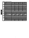
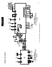
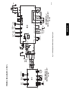
CONNECTION DIAGRAMS
CONNECTING CABLE
Main Power
Supply
115-1-60
L
NL
N
GND
S
115-1-60
Power to
Indoor
Unit
Ground Control
9 &12K Outdoor Unit
9 &12K Indoor Unit
LN
GND
S
Power to
Indoor
Unit
115-1-60
Ground Control
Use a four (4) Wire Cable
(Do Not use thermostat wire)
A08292
Fig. 7 – Connection Diagrams
38/40GXQ