


16
TROUBLESHOOTING
This section provides the required flow charts to troubleshoot problems that may arise.
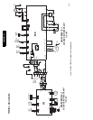
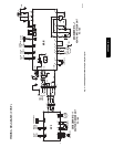
NOTE: Information required in the diagnoses can be found either on the wiring diagrams or in the appendix.
Required
Tools:
The following tools are needed when diagnosing the units:
S Digital multimeter
S Screw drivers (Phillips and straight head)
S Needle--nose pliers
Recommended
Steps
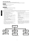
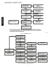
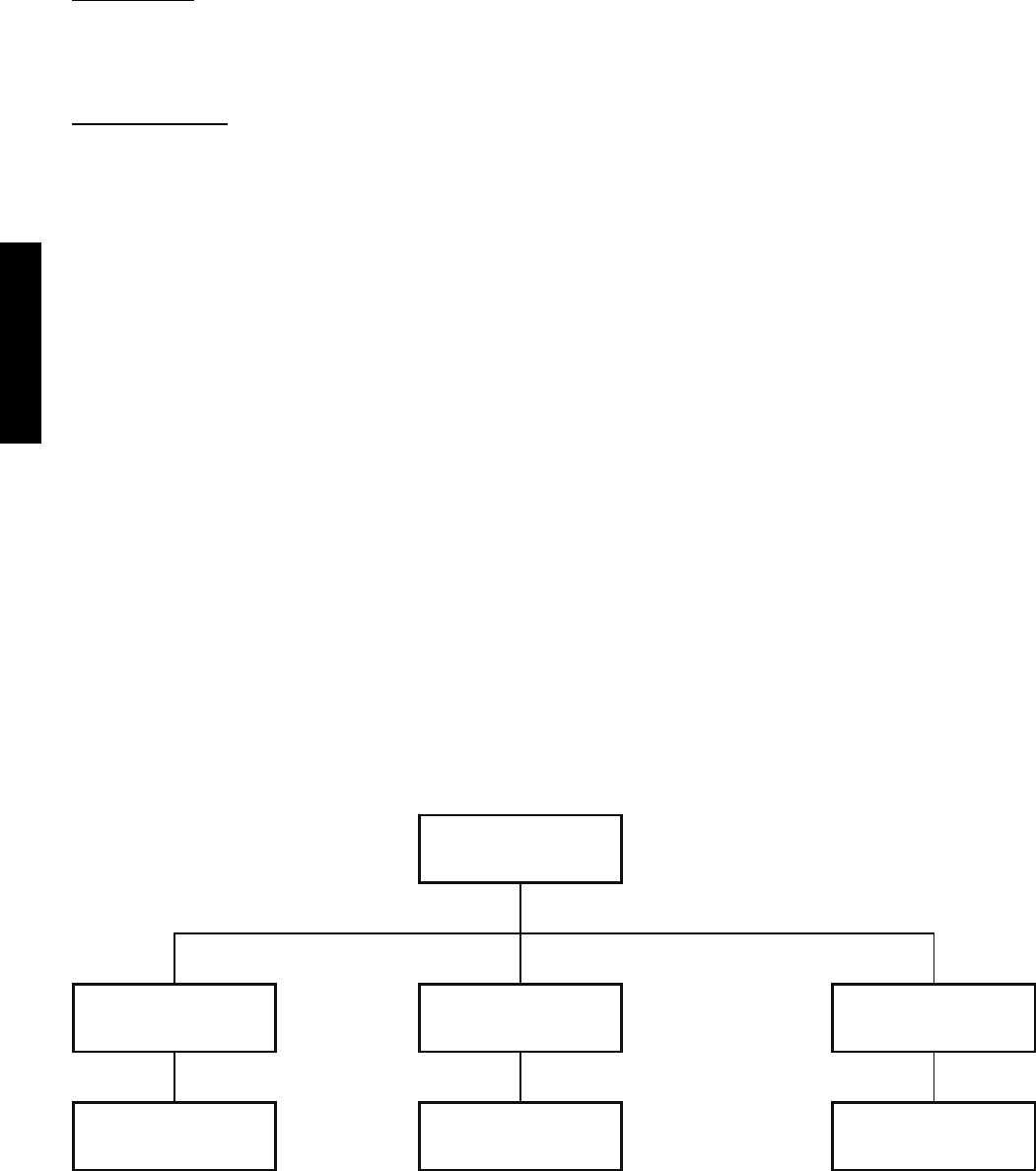
1. Refer to the diagnostic hierarchy chart below and determine
the problem at hand.
2. Go to the chart listed in the diagnostic hierarchy and follow
the steps in the chart for the selected problem.
Error codes, if they occur, are displayed on the LED panel on the front cover of the unit. In addition, some of the same errors are displayed
by flashing LEDs on the outdoor board. If possible, always check the diaganostic codes displayed on the indoor unit first.
For problems requiring measurements at the control boards:
1. Always disconnect the main power.
2. When possible check the outdoor board first.
3. Start by removing the outdoor unit top cover.
4. Reconnect the main power
5. Probe the outdoor board inputs and outputs with a digital
multi--meter referring to the wiring diagrams and
input/output charts found in the appendix.
6. Connect the red probe to hot signal and the black probe to
the ground or negative.
7. Note that some of the DC voltage signals are pulse will give
continuously variable readings.
8. If it is necessary to check the indoor unit board you must
start by disconnecting the main power.
9. Next remove the front cover of the unit and then control
box cover.
10. Carefully remove the indoor board from the control box,
place it face up on a plastic surface (not metal).
11. Reconnect the main power and repeat steps 5,6, and 7.
12. Disconnect main power before reinstalling board to avoid
shock hazard and board damage.
For problems requiring pressure measurements:
1. Connect the low pressure gauge to the gauge connection
port on the suction service valve
2. Set compressor speed using the system remote control as
follows:
COOLING – Select a set point of 66_F and push the sleep
button 4 times
HEATING – Select a set point of 84_F and push the sleep
button 4 times
3. With the system operating at steady state conditions, make
the following measurements:
a. Outdoor ambient temperature
b. Compressor discharge temperature as close to the
compressor as possible
c. Suction pressure
4. Refer to the Appendix and select a suction pressure and
discharge temperature range based on the outdoor ambient
temperature for either cooling or heating. Compare the
measured pressure and temperature to the values in the chart
to determine if the operating pressures and temperatures of
the systems are normal or not.
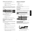
Unit has a problem
Unit displays a
diagnostic code
Unit not running and
no diagnostic code
Unit running but not
optimally
Refer to page ---, identify
error code and use
appropriate diagnostic chart
Go to chart # 8 Go to chart # 9 &10
Unit has a problem
Unit displays a
diagnostic code
Unit not running and
no diagnostic code
Unit running but not
optimally
Refer to page ---, identify
error code and use
appropriate diagnostic chart
Go to chart # 8 Go to chart # 9 &10
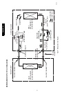
A09359
Fig. 27 – Diagnostic Hierarchy
38/40GXC(Q)