


11
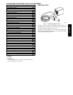
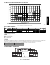
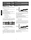
REFRIGERANT LI NES
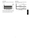
Routing – Refrigerant lines can be routed in any of the four
directions shown in Fig. 10.
1
Right Exit
2
Right Rear Exit
3LeftExit
4
Left Rear Exi
(a)
(b)
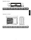
A
s viewed from front
Fig. 11 – Refrigerant Line Routing
A08281
General Guidelines:
1. The 38GXQ units are shipped with full charge of R--410A
refrigerant. All charges, line sizing, and capacities are based
on runs of 25ft (7.6 m). For runs over 25ft (7.6 m), consult
long line section for charge adjustments.
2. Refrigerant lines should not be buried in the ground. If it is
necessary to bury the lines, not more than 36 inches (914
mm) should be buried. Provide a minimum of 6 inch (152
mm) vertical rise to service valves to prevent refrigerant
migration.
3. Both lines must be insulated. Use a minimum of 1/2 inch
(12.7 mm) thick insulation. Closed--cell insulation is
recommended in all long--line applications.
4. Special consideration should be given to isolating
interconnecting tubing from the building structure. Isolate
the tubing so that vibration or noise is not transmitted into
the structure.
Long Line
Applications:
1. A field fabricated wind baffle is recommended.
2. No change in line sizing is required.
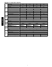
3. Add refrigerant per table below.
ADDITIONAL CHARGE TABLE
Unit Size
Additional Charge, oz./ft
ft (m)
10 --- 25
(3.05 --- 7.62)
>25 --- 65
(7.62---19.81)
9K hp
None 0.48
12K hp
4. Reduction in capacity due to long lines can be calculated
from the chart below.
CAPACITY LOSS
Capacity,% Loss
Line Length, ft (m)
Cooling:
25
(7.62)
45
(13.7)
65
(19.8)
9&12KBTU/Hmodels 0% 2% 5%
Heating:
9&12KBTU/Hmodels 0% 7% 11%
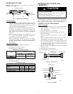
SYSTEM EVACUATION AND
CHARGING
UNIT DAMAGE HAZARD
Failure to follow this caution may result in equipment
damage or improper operation.
Never use the system compressor as a vacuum pump.
CAUTION
!
Refrigerant tubes and indoor coil should be evacuated using the
recommended deep vacuum method of 500 microns. The alternate
triple evacuation method may be used if the procedure outlined
below is followed. Always break a vacuum with dry nitrogen.
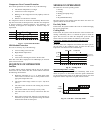
SYSTEM VACUUM AND CHARGE
Using Vacuum Pump
1. Completely tighten flare nuts A, B, C, D, connect manifold
gage charge hose to a charge port of the low side service
valve. (See Fig. 15.)
2. Connect charge hose to vacuum pump.
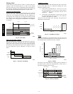
3. Fully open the low side of manifold gage. (See Fig. 16)
4. Start vacuum pump
5. Evacuate using either deep vacuum or triple evacuation
method.
6. After evacuation is complete, fully close the low side of
manifold gage and stop operation of vacuum pump.
7. The factory charge contained in the outdoor unit is good for
up to 25 ft. (8 m) of line length. Forrefrigerant lines longer
than 25 ft (8 m), add 0.1 oz. per foot of extra piping up to
the maximum allowable length.
8. Disconnect charge hose from charge connection of the low
side service valve.
9. Fully open service valves B and A.
10. Securely tighten caps of service valves.
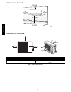
Outdoor Unit
Indoor Uni
t
Refrigerant
Service Valve
Low Side
High Side
A
B
C
D
A07360
Fig. 12 – Service Valve
Manifold Gage
500 microns
Low side valve
High side valve
Charge hose
Charge hose
Vacuum pump
Low side valve
A07361
Fig. 13 – Manifold
38/40GXC(Q)