


Do not vent refrigerant to atmosphere. Recover during system
repair or final unit disposal.
1. If equipped with a crankcase heater, energize a minimum of
24 hr before starting unit. To energize heater only, set
thermostat OFF and close electrical disconnect to outdoor
unit.
2. Fully open liquid and vapor service valves.
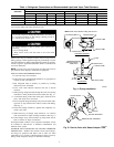
3. Unit is shipped with valve stem(s) front seated and caps
installed. Replace stem caps after system is opened to refrig-
erant flow. Replace caps finger tight and tighten additional 1/6
turn using a backup wrench on valve body flats to prevent
distortion of sheet metal.
4. Close electrical disconnects to energize system.
5. Set room thermostat at desired temperature.
6. Set room thermostat to HEAT or COOL and fan to ON or
AUTO mode, as desired. Operate unit for 15 minutes. Check
system refrigerant charge.
7. Factory charge is shown on unit rating plate. Adjust charge in
cooling mode by following procedure shown in charging
table. Check charge in heating mode by following procedure
shown on heating check chart. Both are located on unit.
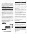
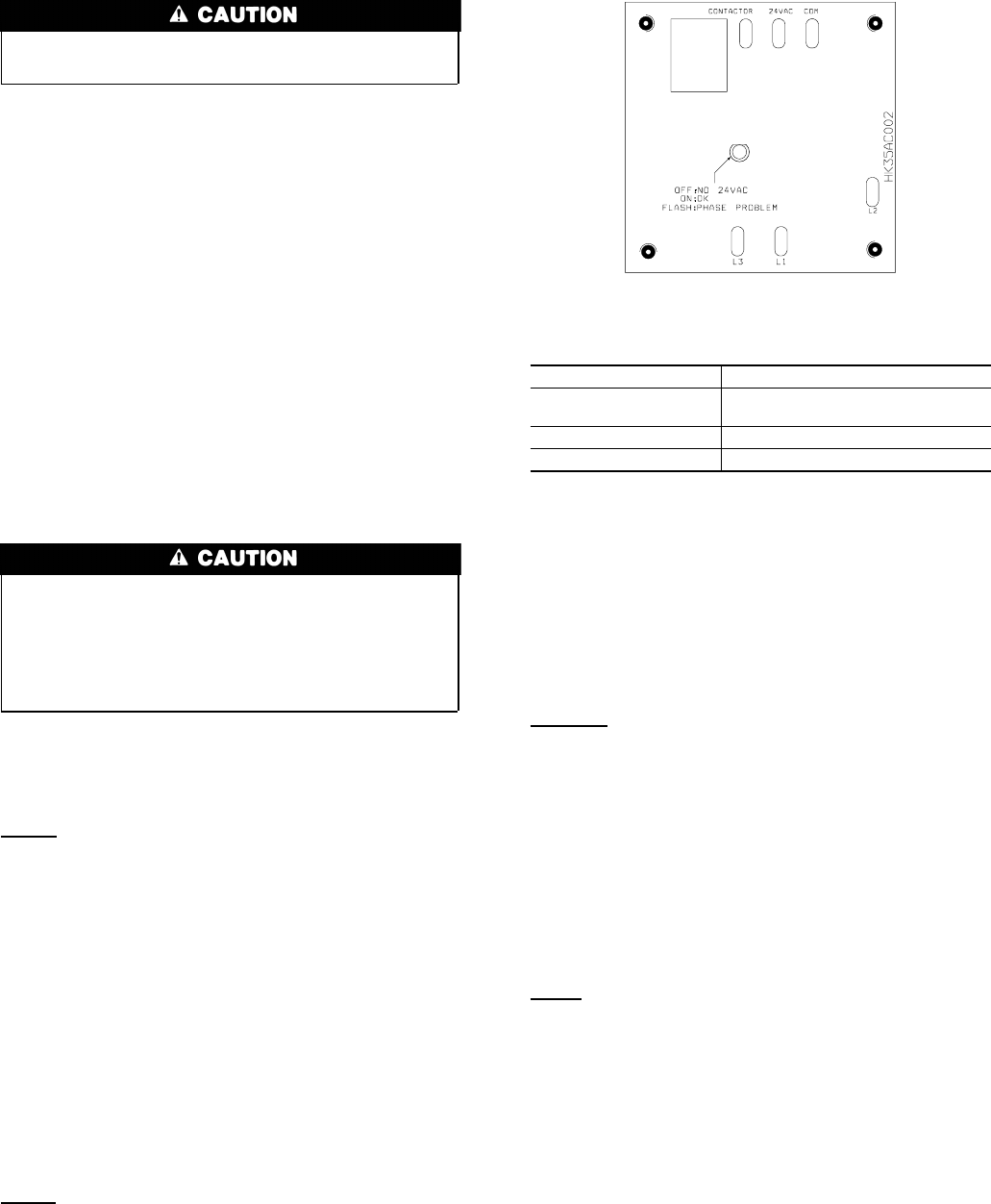
• 3-phase scroll compressors are rotation sensitive.
• A flashing LED on phase monitor indicates reverse rotation.
(See Fig. 8 and Table 2.)
• This will not allow contactor to be energized.
• Disconnect power to unit and interchange 2 field wiring
leads on unit contactor.
SEQUENCE OF OPERATION — With power supplied to indoor
and outdoor units, transformer is energized. Defrost control board
is equipped with 5-minute lockout timer which may be initiated
upon any interruption of power.
Cooling
On a call for cooling, the thermostat makes circuits R-O, R-Y, and
R-G. Circuit R-O energizes reversing valve, switching it to cooling
position. On three phase models with scroll compressors, the units
are equipped with a phase monitor to detect if the incoming power
is correctly phased for compressor operation. (See Fig. 8 and Table
2.) If phasing is correct, circuit R-Y energizes contactor, starting
outdoor fan motor and compressor circuit. R-G energizes indoor
unit blower relay, starting indoor blower motor on high speed.
NOTE: If the phasing is incorrect, the contactor will not be
energized. To correct the phasing, interchange any two of the three
power connections on the field side.
When thermostat is satisfied, its contacts open, de-energizing
contactor and blower relay. Compressor and motors stop.
NOTE: If indoor unit is equipped with a time-delay relay circuit,
the blower runs an additional 90 sec to increase system efficiency.
Heating
On a call for heating, the thermostat makes circuits R-Y and R-G.
If phasing is correct, circuit R-Y energizes contactor, starting
outdoor fan motor and compressor. Circuit R-G energizes indoor
blower relay, starting blower motor on high speed.
Should the temperature continue to fall, R-W2 is made through the
second-stage room thermostat bulb. Circuit R-W2 energizes a
sequencer, bringing on the first bank supplemental electric heat
and providing electrical potential to the second heater sequencer (if
used). If outdoor temperature falls below the setting of the outdoor
thermostat (field-installed option), contacts close to complete the
circuit and bring on the second bank of supplemental electric heat.
When the thermostat is satisfied, its contacts open, de-energizing
contactor and sequencer. All heaters and motors should stop.
Quiet Shift
Quiet Shift is a field-selectable defrost mode, which will eliminate
occasional noise that could be heard at the start of the defrost cycle
and restarting of heating cycle. It is selected by placing DIP switch
3 (on defrost board) in ON position.
When Quiet Shift switch is placed in ON position, and a defrost is
initiated, the following sequence of operation will occur. Revers-
ing valve will energize, compressor will turn off for 30 sec, then
turn back on to complete defrost. At the start of heating cycle after
conclusion of defrost mode, reversing valve will de-energize, the
compressor will turn off for another 30 sec, and the fan will turn
off for 40 sec, before starting in the heating mode.
Defrost
The defrost control is a time/temperature control which includes a
field-selectable time period (DIP switch 1 and 2 on the board)
between defrost cycles of 30, 60, 90, or 120 minutes (factory set at
90 minutes).
To initiate a forced defrost, two options are available depending on
the status of the defrost thermostat.
If defrost thermostat is closed, speedup pins (J1) must be shorted
by placing a flat head screwdriver in between for 5 sec and
releasing, to observe a complete defrost cycle. When the Quiet
Shift switch is selected, compressor will be turned off for two 30
sec intervals during this complete defrost cycle as explained
previously. When Quiet Shift switch is in factory default OFF
position, a normal and complete defrost cycle will be observed.
Table 2—Phase Monitor LED Indicators
LED STATUS
OFF
No call for compressor
operation
FLASHING Reversed phase
ON Normal
Fig. 8—Phase Monitor Control
A00010
6
→
→