


To prevent compressor damage DO NOT bury more than 36
in. of refrigerant tubing. If ANY tubing is buried, provide 6
in. vertical rise at service valve.
To prevent damage to unit or service valves observe the
following:
• Use a brazing shield.
• Wrap service valves with wet cloth or use a heat sink
material.
Outdoor units may be connected to indoor section using accessory
tubing package or field-supplied refrigerant grade tubing of correct
size and condition. For tubing requirements beyond 50 ft (15.24m),
consult Long-Line Application Guideline which is available from
your local distributor.
NOTE: In some cases noise in the living area has been traced to
gas pulsations from improper installation of equipment.
INSTALLATION RECOMMENDATIONS
1. Locate unit away from windows.
2. Ensure that vapor and liquid tube diameters are appropriate to
capacity of unit. (See Table 1.)
3. Run refrigerant tubes as directly as possible by avoiding
unnecessary turns and bends.
4. Leave some slack between structure and unit to absorb
vibration.
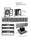
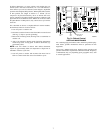
5. When passing refrigerant tubes through the wall, seal opening
with RTV or other pliable silicon-based caulk. (See Fig. 4.)
6. Avoid direct tubing contact with water pipes, ductwork, floor
joists, wall studs, floors, and walls.
7. Do not suspend refrigerant tubing from joists and studs with a
rigid wire or strap which comes in direct contact with tubing.
(See Fig. 4.)
8. Ensure that tubing insulation is pliable and completely sur-
rounds vapor tube.
9. When necessary, use hangar straps which are 1 in. (25mm)
wide and conform to shape of tubing insulation. (See Fig. 4.)
10. Isolate hangar straps from insulation by using metal sleeves
bent to conform to shape of insulation.
If refrigerant tubes or indoor coil is exposed to atmosphere, it must
be evacuated to 500 microns to eliminate contamination and
moisture in the system.
OUTDOOR UNIT CONNECTED TO FACTORY-APPROVED
INDOOR UNIT — Outdoor unit contains correct system refriger-
ant charge for operation with indoor unit of same size when
connected by 15 ft (4.55m) of field-supplied or factory-accessory
tubing. Check refrigerant charge for maximum efficiency.
Table 1—Refrigerant Connections and Recommended Liquid and Vapor Tube Diameters
UNIT SIZE
LIQUID VAPOR
Connection Dia. Tube Dia. Connection DIia. Vapor Dia.
In. mm In. mm In. mm In. mm
024 3/8 9.53 3/8 9.53 5/8 15.88 5/8 15.88
036 3/8 9.53 3/8 9.53 3/4 19.05 3/4 19.05
048 3/8 9.53 3/8 9.53 7/8 22.23 7/8 22.23
060 3/8 9.53 3/8 9.53 7/8 22.23 1-1/8 28.58
NOTES: 1. Tube diameters are for lengths up to 50 ft (15.24m). For tubing lengths greater than 50 ft (15.24m), consult Long-Line Application Guideline.
2. Do not apply capillary tube indoor coils to these units.
Fig. 4—Piping Installation
A94330
INSULATION
VAPOR TUBE
LIQUID TUBE
OUTDOOR WALL INDOOR WALL
LIQUID TUBE
VAPOR TUBE
INSULATION
CAULK
Avoid contact between tubing and structure.NOTE:
THROUGH THE WALL
HANGER STRAP
(AROUND VAPOR
TUBE ONLY)
JOIST
1″ MIN
(25 mm)
SUSPENSION
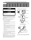
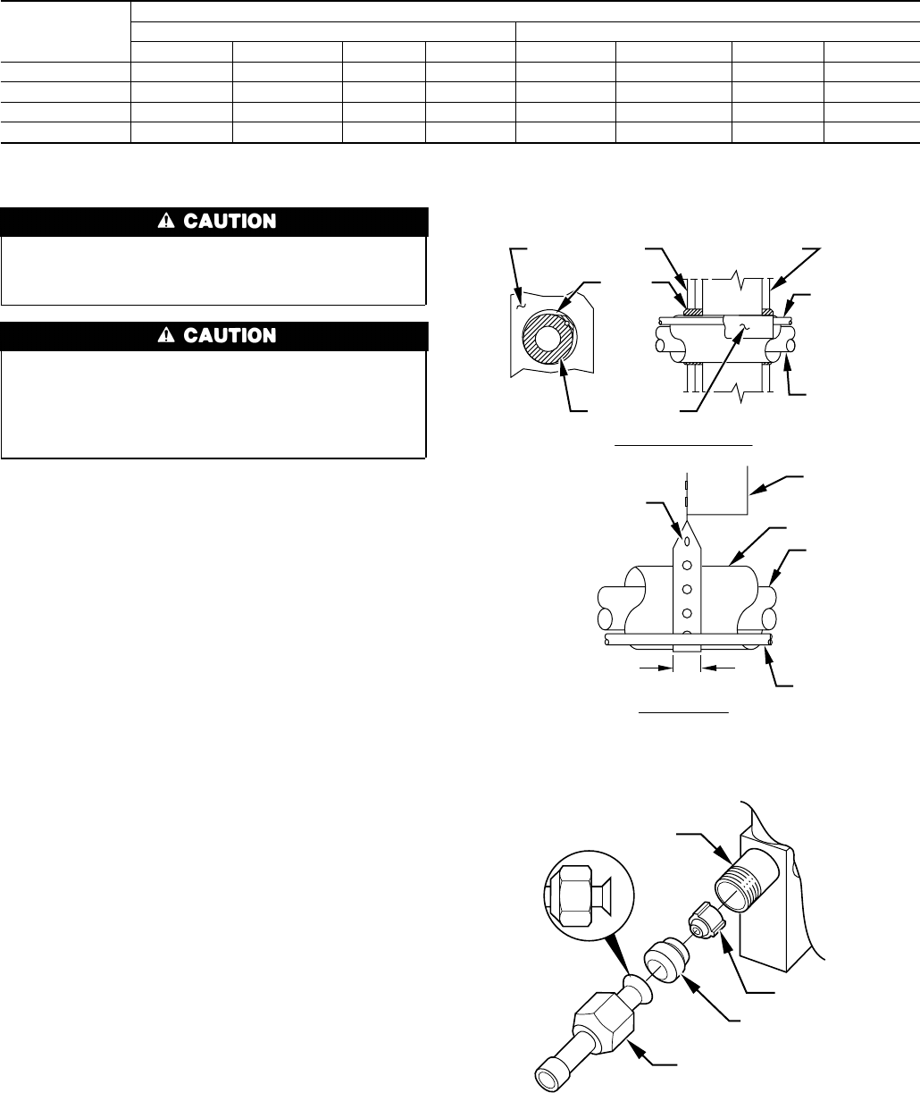
Fig. 5—Service Valve with Sweat Adapter Tube
A94029
PISTON BODY
PISTON
PISTON RETAINER
SWEAT/FLARE ADAPTER
3