match, replace indoor coil piston with piston shipped with outdoor
unit. The piston shipped with outdoor unit is correct for any
approved indoor coil combination.
Do not operate unit in the vicinity of toxic or flammable
material. Failure to follow this warning can result in personal
injury, fire, or death.
Remove indoor coil piston if unit is to be installed on system
with a TXV metering device.
Step 5—Make Piping Connections
Relieve pressure and recover all refrigerant before system
repair or final unit disposal to avoid personal injury or death.
Use all service ports and open all flow-control devices,
including solenoid valves.
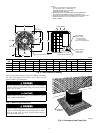
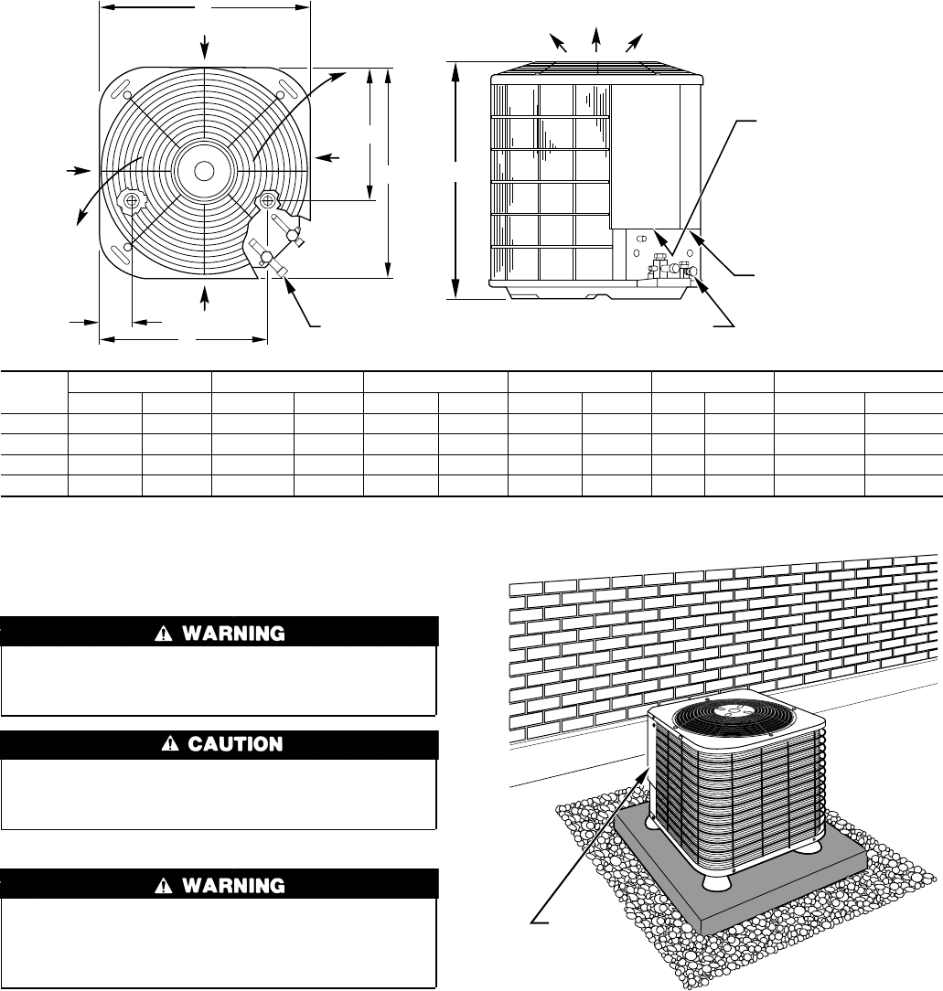
Fig. 2—Unit Reference Drawing
UNIT
SIZE
A/B C D E F G
In. mm In. mm In. mm In. mm In. mm In. mm
024 22-1/2 571.5 3-11/16 93.6 18-1/8 460.4 14-3/8 365.1 5/8 15.88 33-15/16 862.0
036 30 762.0 6-1/2 165.1 23-1/2 596.9 20 508.0 3/4 19.05 39-15/16 1014.4
048 30 762.0 6-1/2 165.1 23-1/2 596.9 20 508.0 7/8 22.23 33-15/16 862.0
060 30 762.0 6-1/2 165.1 23-1/2 596.9 20 508.0 7/8 22.23 33-15/16 862.0
A97004
AIR DISCHARGE
3
/
8
″ DIA LIQUID LINE CONN
FIELD CONTROL
SUPPLY CONN
7
/
8
″ DIA HOLE
AIR
DISCHARGE
AIR
DISCHARGE
AIR IN
AIR IN
1. ALLOW 30″ CLEARANCE TO SERVICE END OF
UNIT, 48″ ABOVE UNIT, 6″ ON ONE SIDE, 12″
ON REMAINING SIDE, AND 24″ BETWEEN
UNITS FOR PROPER AIRFLOW.
2. MINIMUM OUTDOOR OPERATING AMBIENT IN COOLING MODE IS
55° F (UNLESS LOW AMBIENT CONTROL IS USED) MAX. 115° F.
3. MAXIMUM OUTDOOR OPERATING AMBIENT IN HEATING MODE IS 66° F.
4. SERIES DESIGNATION IS THE 13TH POSITION OF THE UNIT
MODEL NUMBER.
NOTES:
FIELD POWER
SUPPLY CONN
7
/
8
″ DIA HOLE WITH
1
1
/
8
″ DIA KNOCKOUT
AND 1
3
/
8
″ DIA KNOCKOUT
A
D
AIR IN
E
B
AIR
IN
C
F DIA SUCTION LINE CONN
G
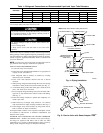
Fig. 3—Accessory Heat Pump Feet
A97006
SERVICE
ACCESS
2


