


SEQUENCE OF OPERATION
NOTE: Defrost-control board is equipped with 5-minute lockout
timer that may be initiated upon any interruption of power.
With power supplied to indoor and outdoor units, transformer is
energized.
Cooling
On a call for cooling, thermostat makes circuits R-O, R-Y, and
R-G. Circuit R-O energizes reversing valve, switching it to cooling
position. On 3-phase models with scroll compressors, the units are
equipped with a phase monitor to detect if the incoming power is
correctly phased for compressor operation. If phasing is correct,
circuit R-Y energizes contactor, starting outdoor-fan motor and
compressor circuit. R-G energizes indoor unit-blower relay, start-
ing indoor-blower motor on high speed.
NOTE: If the phasing is incorrect, the contactor will not be
energized. To correct the phasing, interchange any 2 of the 3
power connections on the field side.
When thermostat is satisfied, its contacts open, de-energizing the
contactor and blower relay. Compressor and motors should stop.
NOTE: If indoor unit is equipped with a time-delay relay circuit,
the blower runs an additional 90 sec to increase system efficiency.
Heating
On a call for heating, thermostat makes circuits R-Y and R-G. If
phasing is correct, circuit R-Y energizes contactor, starting
outdoor-fan motor and compressor. Circuit R-G energizes indoor-
blower relay, starting blower motor on high speed.
Should temperature continue to fall, R-W2 is made through
second-stage room-thermostat bulb. Circuit R-W2 energizes a
sequencer, bringing on first bank of supplemental electric heat and
providing electrical potential to second heater sequencer (if used).
If outdoor temperature falls below setting of outdoor thermostat
(field-installed option), contacts close to complete circuit and bring
on second bank of supplemental electric heat.
When thermostat is satisfied, its contacts open, de-energizing
contactor and sequencer. All heaters and motors should stop.
When the thermostat is satisfied, its contacts open, de-energizing
contactor and sequencer. All heaters and motors should stop.
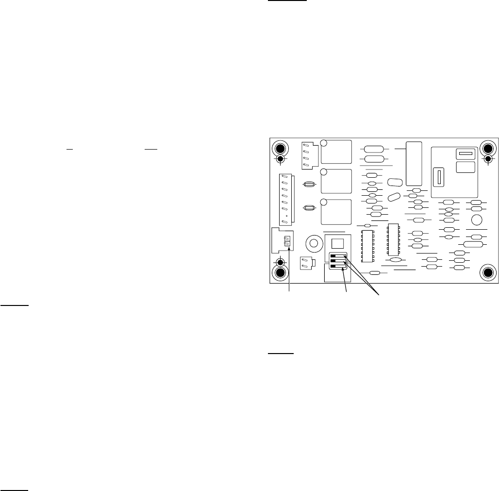
Quiet Shift
Quiet Shift is a field-selectable defrost mode, which will eliminate
occasional noise that could be heard at the start of the defrost cycle
and restarting of heating cycle. It is selected by placing DIP switch
3 (on defrost board) in ON position.
When Quiet Shift switch is placed in ON position, and a defrost is
initiated, the following sequence of operation will occur. Revers-
ing valve will energize, compressor will turn off for 30 sec, then
turn back on to complete defrost. At the start of heating cycle after
conclusion of defrost mode, reversing valve will de-energize, the
compressor will turn off for another 30 sec, and the fan will turn
off for 40 sec, before starting in the heating mode.
Defrost
The defrost control is a time/temperature control which includes a
field-selectable time period (DIP switch 1 and 2 on the board)
between defrost cycles of 30, 60, 90, or 120 minutes (factory set at
90 minutes).
To initiate a forced defrost, two options are available depending on
the status of the defrost thermostat.
If defrost thermostat is closed, speedup pins (J1) must be shorted
by placing a flat head screwdriver in between for 5 sec and
releasing, to observe a complete defrost cycle. When the Quiet
Shift switch is selected, compressor will be turned off for two 30
sec intervals during this complete defrost cycle as explained
previously. When Quiet Shift switch is in factory default OFF
position, a normal and complete defrost cycle will be observed.
If defrost thermostat is in open position, and speedup pins are
shorted (with a flat head screwdriver) for 5 sec and released, a
short defrost cycle will be observed (actual length is dependent
upon the selected Quiet Shift position). When Quiet Shift switch is
in ON position, the length of defrost is 1 minute (30 sec
compressor off period followed by 30 sec of defrost with com-
pressor operation). On return to heating operation, compressor will
again turn off for an additional 30 sec and the fan for 40 sec. When
the Quiet Shift is in OFF position, only a brief 30 sec cycle will be
observed.
WIRING DIAGRAM NOTES:
1. CARRIER THERMOSTAT-WIRING DIAGRAMS ARE
ONLY ACCURATE FOR MODEL NUMBERS BEGINNING
WITH TSTAT_______.
2. WIRING MUST CONFORM TO NEC OR LOCAL CODES.
3. SOME UNITS ARE EQUIPPED WITH PRESSURE
SWITCH(ES), TEMPERATURE SWITCH, OR 5–MINUTE
COMPRESSOR-CYCLE PROTECTION. CONNECT 24V
FIELD WIRING TO FACTORY-PROVIDED STRIPPED
LEADS.
4. THERMOSTATS ARE FACTORY CONFIGURED WITH
5-MINUTE COMPRESSOR-CYCLE PROTECTION AND
4-CYCLES-PER-HR LIMIT. SEE THERMOSTAT-
INSTALLATION INSTRUCTIONS FOR DETAILS.
5. TO STAGE ELECTRIC-RESISTANCE HEAT, CONSULT
OUTDOOR THERMOSTAT-INSTALLATION INSTRUC-
TIONS.
6. UNDERLINED LETTER ON DUAL TERMINAL INDI-
CATES ITS USAGE.
FOR EXAMPLE: O/W2 MEANS O; O/W2MEANS W2
7. OUTDOOR-TEMPERATURE SENSOR MUST BE AT-
TACHED IN ALL DUAL-FUEL INSTALLATIONS. JUMPER
WIRE BETWEEN O/W2 AND L THERMOSTAT TERMINALS
MUST BE PRESENT.
8. Y1 AND O CONNECTIONS TO 2–STAGE FURNACES
MAY NOT EXIST OR MAY ONLY BE A WIRE RATHER
THAN A SCREW TERMINAL.
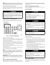
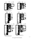
Fig. 8—Defrost Control
A91444
OF2
CESO130076–00
OF1
ON
QUIET
SHIFT
120
30
60
60
30
90
INTERVAL TIMER
OFF
P3
DFT
O R W
2
Y C
T2 C C O
DFT
T1 Y
P1
J1
SPEEDUP
Speedup
Pins
Defrost interval
DIP switches
Quiet
Shift
7
→
→
→