


Step 8—Make Piping Connections
Relieve pressure and recover all refrigerant before system
repair or final unit disposal to avoid personal injury or death.
Use all service ports and open all flow-control devices,
including solenoid valves.
If ANY refrigerant tubing is buried, provide a 6 in. vertical
rise at service valve. Refrigerant tubing lengths up to 36 in.
may be buried without further special consideration. For
lengths above 36 in., consult your local distributor.
To prevent damage to unit or service valves observe the
following:
•Use a brazing shield.
•Wrap service valves with wet cloth or use a heat-sink
material.
Outdoor units may be connected to indoor section using accessory-
tubing package or field-supplied refrigerant-grade tubing of cor-
rect size and condition. For tubing requirements beyond 50 ft
length or 20 ft vertical differential, substantial capacity and
performance losses can occur. Following the recommendations in
the Residential Split-System Long-Line Application Guideline
will reduce these losses. Refer to Table 1 for field-tubing diam-
eters.
REFRIGERANT TUBING
Connect tubing to fittings on outdoor unit vapor- and liquid-
service valves. (See Table 1.) Use refrigerant-grade tubing. Refer
to appropriate section below for type of service valves installed on
unit.
SWEAT CONNECTION
To avoid valve damage while brazing, service valves must be
wrapped in a heat-sinking material such as a wet cloth.
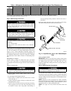
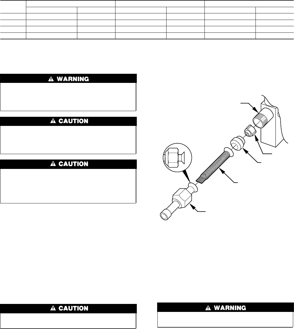
1. Remove plastic retainer holding outdoor piston in liquid-
service valve.
2. Locate adapter tube shipped with unit.
3. Install strainer in adapter tube and connect tube to service
valve. (See Fig. 4.)
4. Connect refrigerant tubing to fittings on outdoor-unit vapor-
and liquid-service valves.
5. Service valves are closed from factory and ready for brazing.
After wrapping service valve with a wet cloth, tubing set can
be brazed to service valve using either silver-bearing or
non-silver-bearing brazing material. Consult local code re-
quirements.
Refrigerant tubing and indoor coil are now ready for leak testing.
This check should include all field and factory joints.
FINAL TUBING CHECK
IMPORTANT: Check to be certain factory tubing on both indoor
and outdoor unit has not shifted during shipment. Ensure tubes are
not rubbing against each other or any sheet metal. Pay close
attention to feeder tubes, making sure wire ties on feeder tubes are
secure and tight.
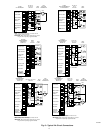
Step 9—Make Electrical Connections
To avoid personal injury or death, do not supply power to unit
with compressor terminal-box cover removed.
Be sure field wiring complies with local and national fire, safety,
and electrical codes, and voltage to system is within limits shown
on unit-rating plate. Contact local power company for correction of
improper voltage. See unit-rating plate for recommended circuit-
protection device.
NOTE: Operation of unit on improper line voltage constitutes
abuse and could affect unit reliability. See unit-rating plate. Do not
install unit in system where voltage or phase imbalance (3 phase)
may fluctuate above or below permissible limits.
NOTE: Use copper wire only between disconnect switch and
unit.
Table 1—Refrigerant Connections and Recommended Liquid- and Vapor-Tube Diameters (In.)
UNIT
SIZE
LIQUID VAPOR VAPOR (LONG LINE)
Connection Diameter Tube Diameter Connection Diameter Tube Diameter Connection Diameter Tube Diameter
018, 024 3/8 3/8 3/4 3/4 3/4 3/4
030, 036 3/8 3/8 3/4 3/4 3/4 7/8
042, 048 3/8 3/8 7/8 7/8 7/8 1-1/8
060 3/8 3/8 7/8 1-1/8 7/8 1-1/8
NOTES:
1. Tube diameters are for lengths up to 50 ft. For tubing lengths greater than 50 ft, consult Long Line section of the Application Guideline.
2. Do not apply capillary-tube indoor coils to these units.
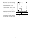
Fig. 4—Liquid-Service Valve with Sweat-Adapter
Tube
A97512
PISTON BODY
PISTON
PISTON
RETAINER
SWEAT/FLARE ADAPTER
STRAINER
3