


NOTE: Install branch-circuit disconnect of adequate size per
NEC to handle unit-starting current. Locate disconnect within sight
from and readily accessible from unit, per Section 440-14 of NEC.
ROUTE GROUND AND POWER WIRES
Remove access panel and control box to gain access to unit wiring.
Extend wires from disconnect through power-wiring hole provided
and into unit-control box.
The unit cabinet must have an uninterrupted or unbroken
ground to minimize personal injury if an electrical fault
should occur. The ground may consist of electrical wire or
metal conduit when installed in accordance with existing
electrical codes. Failure to follow this warning can result in an
electric shock, fire, or death.
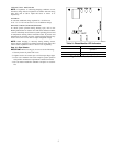
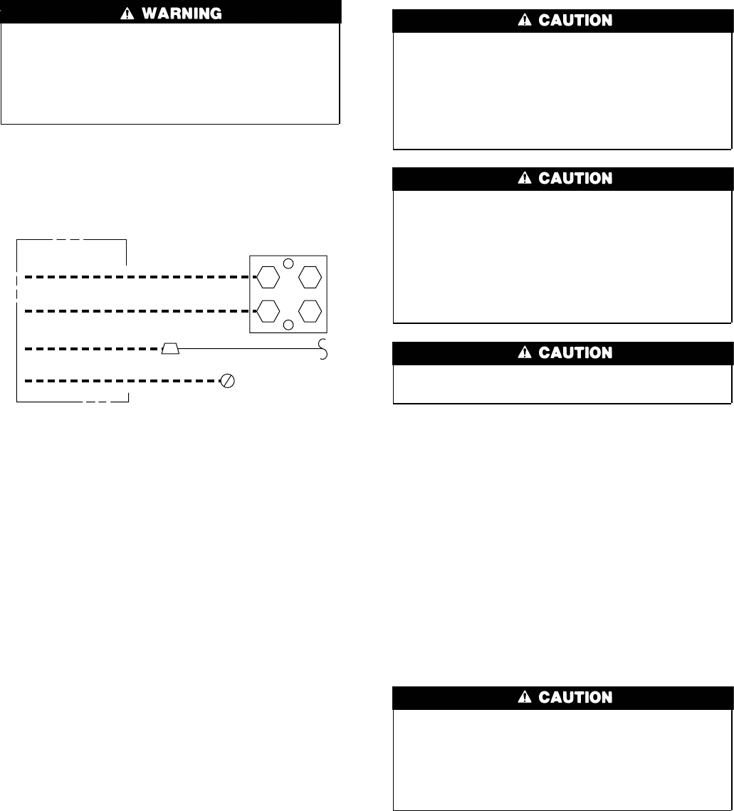
CONNECT GROUND AND POWER WIRES
Connect ground wire to ground connection in control box for
safety. Connect power wiring to contactor as shown in Fig. 5.
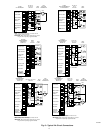
CONNECT CONTROL WIRING
Route 24v control wires through control-wiring grommet and
connect leads to control wiring. Refer also to Installation Instruc-
tions packaged with thermostat.
Use No. 18 AWG color-coded, insulated (35°C minimum) wire. If
thermostat is located more than 100 ft from unit, as measured
along the control-voltage wires, use No. 16 AWG color-coded
wire to avoid excessive voltage drop.
All wiring must be NEC Class 1 and must be separated from
incoming power leads.
Use furnace transformer, fan-coil transformer, or accessory trans-
former for control power, 24v/40va minimum.
NOTE: Use of available 24v accessories may exceed the mini-
mum 40va power requirement. Determine total transformer load-
ing and increase the transformer capacity or split the load with an
accessory transformer as required.
FINAL WIRING CHECK
IMPORTANT: Check factory wiring and field-wire connections
to ensure terminations are secured properly. Check wire routing to
ensure wires are not in contact with tubing, sheet metal, and so
forth.
Step 10—Compressor Crankcase Heater
When equipped with a crankcase heater, furnish power to heater a
minimum of 24 hr before starting unit. To furnish power to heater
only, set thermostat to OFF and close electrical disconnect to
outdoor unit. A crankcase heater is required if refrigerant tubing is
longer than 50 ft.
Step 11—Install Electrical Accessories
Refer to the individual instructions packaged with kits or acces-
sories when installing.
Step 12—Start-Up
To prevent compressor damage or personal injury, observe
the following:
•Do not overcharge system with refrigerant.
•Do not operate unit in a vacuum or at negative pressure.
•Do not disable low-pressure switch.
In scroll compressor applications:
•Dome temperatures may be hot.
To prevent personal injury wear safety glasses, protective
clothing, and gloves when handling refrigerant and observe
the following:
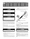
•Back-seating service valves are not equipped with Schrader
valves. Fully back seat (counterclockwise) valve stem before
removing gage-port cap.
•Front-seating service valves are equipped with Schrader
valves.
Do not vent refrigerant to atmosphere. Recover during system
repair or final unit disposal.
If refrigerant tubes or indoor coil are exposed to atmosphere, they
must be evacuated to 500 microns to eliminate contamination and
moisture in the system.
Follow these steps to properly start up the system:
1. Fully back seat (open) liquid- and vapor-tube service valves.
2. Unit is shipped with valve stem(s) front seated (closed) and
caps installed. Replace stem caps after system is opened to
refrigerant flow. Replace caps finger-tight and tighten with
wrench an additional 1/12 turn.
3. Close electrical disconnects to energize system.
4. Set room thermostat to desired temperature. Be sure set point
is below indoor ambient temperature.
5. Set room thermostat to HEAT or COOL and fan control to ON
or AUTO, as desired. Operate unit for a minimum of 15
minutes. Check system refrigerant charge.
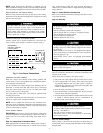
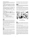
•3-phase scroll compressors are rotation sensitive.
•A flashing LED on phase monitor indicates reverse rotation.
(See Fig. 7 and Table 2.)
This will not allow contactor to be energized.
•Disconnect power to unit and interchange 2 field-wiring
leads on unit contactor.
Step 13—Check Charge
Factory charge is shown on unit-rating plate. To check charge in
cooling mode, refer to Cooling-Only Procedure on unit wiring and
charging label.
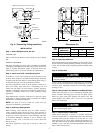
Fig. 5—Line Power Connections
A94025
DISCONNECT
PER N.E.C. AND/OR
LOCAL CODES
CONTACTOR
GROUND
LUG
FIELD GROUND
WIRING
FIELD POWER
WIRING
BLUE
3 PHASE ONLY
4