


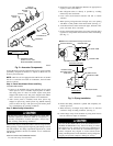

Step 7—Refrigerant Tubing
Connect vapor tube to fitting on outdoor unit vapor service valve
and connect liquid tube to filter drier. (See Fig. 5.)
A brazing shield MUST be used when tubing sets are being
brazed to the service valves to prevent damage to the painted
unit surface.
Relieve pressure and recover all refrigerant before system
repair or final unit disposal to avoid personal injury or death.
Use all service ports and open all flow control devices,
including solenoid valves.
To avoid valve damage while brazing, service valves must be
wrapped with a heat-sinking material such as a wet cloth.
SWEAT CONNECTION — Use refrigerant grade tubing. Service
valves are closed from factory and ready for brazing. After
wrapping service valve and filter drier with wet cloth, tubing set
can be brazed to service valve and filter drier using either silver
bearing or non-silver bearing brazing material. Consult local code
requirements. Refrigerant tubing and indoor coil are now ready for
leak testing. This check should include all field and factory joints.
Step 8—Evacuate
Refrigerant tubes and indoor coil should be evacuated using the
recommended deep vacuum method of 500 microns. The alternate
triple evacuation method may be used if the procedure outlined in
the Service Manual is followed. Always break a vacuum with dry
nitrogen.
Never use the system compressor as a vacuum pump.
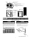
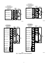
Step 9—Make Electrical Connections
Be sure field wiring complies with local and national fire, safety,
and electrical codes, and voltage to system is within limits shown
on unit rating plate. Contact local power company for correction of
improper voltage. See unit rating plate for recommended circuit
protection device. (See Fig. 4.)
NOTE: Operation of unit on improper line voltage constitutes
abuse and could affect unit reliability. See unit rating plate.
NOTE: Use only copper wire between disconnect switch and
unit.
NOTE: Install branch circuit disconnect per NEC of adequate
size to handle unit starting current, but not larger than maximum
fuse size shown on unit rating plate. Locate disconnect within sight
from and readily accessible from unit, per Section 440-14 of NEC.
ROUTE GROUND AND POWER WIRES — Remove access
panel and control box cover to gain access to unit wiring. Extend
wires from disconnect through power wiring hole provided and
into unit control box. (See Fig. 4.) Size wires per NEC but not
smaller than minimum wire size shown in presale literature.
The cabinet must have an uninterrupted or unbroken ground
according to NEC, ANSI/NFPA 70-1996, or local codes to
minimize personal injury if an electrical fault should occur.
This may consist of electrical wire or conduit approved for
electrical ground when installed in accordance with existing
electrical codes. Failure to follow this warning could result in
an electrical shock, fire, or death.
To avoid personal injury or death, do not supply power to unit
with compressor terminal box cover removed.
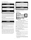
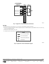
CONNECT GROUND AND POWER WIRES — Connect ground
wire to ground connection in control box for safety. Connect
power wiring to contactor as shown in Fig. 6.
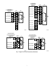
CONNECT CONTROL WIRING — Route 24-v control wires
through control wiring grommet and connect to brown and blue
pigtails supplied in unit splice box. (See Fig. 7.)
Use No. 18 AWG color-coded, insulated (35° C minimum) wire.
If thermostat is located more than 100 ft from unit (as measured
along the control voltage wires), use No. 16 AWG color-coded
wire to avoid excessive voltage drop.
Use furnace transformer, fan coil transformer, or accessory trans-
former for control power, 24v/40va minimum.
NOTE: Use of available 24-v accessories may exceed the mini-
mum 40-va power requirement. Determine total transformer load-
ing and increase transformer capacity or split load with an
accessory transformer as required.
Step 10—Install Electrical Accessories
Refer to individual instructions packaged with kits or accessories
when installing.
Step 11—Start-Up
1. After system is evacuated, fully back seat (open) liquid and
vapor service valves. Unit is shipped with valve stem(s) front
seated and caps installed.
2. Replace stem caps after system is opened to refrigerant flow
(back seated). Replace caps finger tight and tighten additional
1/12 turn with wrench.
3. Close electrical disconnects to energize system.
4. Be sure thermostat set point is below indoor ambient tempera-
ture. Set room thermostat at COOL and fan at ON or AUTO,
as desired. Operate unit for 15 minutes. Check system
refrigerant charge.
Fig. 6—Line Power Connections
A94025
DISCONNECT
PER N.E.C. AND/OR
LOCAL CODES
CONTACTOR
GROUND
LUG
FIELD GROUND
WIRING
FIELD POWER
WIRING
BLUE
3 PHASE ONLY
4