


existing R-22 TXV must be replaced with a factory-approved TXV
specifically designed for R-410A. To replace an R-22 TXV see
accessory kit instructions.
NOTE: FK4 fan coils are equipped with an R-22 TXV. If an FK4
fan coil is used with an R-410A air conditioner, the R-22 TXV
must be replaced.
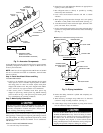
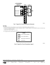
Step 4—Install AccuRater® Piston and Ring
ACCURATER PISTON
1. If unit is to be installed with a piston metering device, check
indoor piston to see if it matches required piston on outdoor
unit rating plate. If it does not match, replace with piston
shipped with outdoor unit. The piston shipped with outdoor
unit is correct for any approved indoor coil combination.
2. After correct piston is installed, locate brass piston ring
shipped in piston bag. Install piston ring behind metering
piston as shown in Fig. 2. The piston ring will ensure piston
stays seated during all operating conditions.
Step 5—Make Piping Connections
Do not leave system open to atmosphere any longer than
minimum required for installation. POE oil in compressor is
extremely susceptible to moisture absorption. Always keep
ends of tubing sealed during installation.
Outdoor units may be connected to indoor sections using accessory
tubing package or field-supplied refrigerant grade tubing of correct
size and condition. For tubing requirements beyond 50 ft, consult
Application Guideline and Service Manual for air conditioners
with R-410A.
INSTALLATION RECOMMENDATIONS
1. Locate unit away from windows.
2. Ensure that vapor and liquid tube diameters are appropriate to
capacity of unit. (See Table 1)
3. Run refrigerant tubes as directly as possible by avoiding
unnecessary turns and bends.
4. Leave some slack between structure and unit to absorb
vibration.
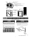
5. When passing refrigerant tubes through wall, seal opening
with RTV or other pliable silicon-based caulk. (See Fig. 3.)
6. Avoid direct lineset contact with water pipes, ductwork, floor
joists, wall studs, floors, and walls.
7. Do not suspend refrigerant tubing from joists and studs with a
rigid wire or strap which comes in direct contact with tubing.
(See Fig. 3.)
8. Ensure that tubing insulation is pliable and completely sur-
rounds vapor line.
9. When necessary, use hanger straps which are 1 in. wide and
conform to shape of tubing insulation. (See Fig. 3.)
10. Isolate hanger straps from insulation by using metal sleeves
bent to conform to shape of insulation.
DO NOT BURY MORE THAN 36 IN. OF REFRIGERANT
TUBING IN GROUND. If any section of tubing is buried,
there must be a 6-in. vertical rise to the valve connections on
the outdoor unit. If more than the recommended length is
buried, refrigerant may migrate to cooler buried section
during extended periods of unit shutdown, causing refrigerant
slugging and possible compressor damage at start-up.
Fig. 2—Accurater Components
A95615
PISTON
BODY
FLARE
ADAPTOR
PISTON
RING
PISTON
PISTON
RETAINER
STRAINER
FIELD
CONNECTION
LIQUID LINE STRAINER
APPROX. 2” LONG
STRAINER LABEL
(AFFIX TO LIQ. LINE
NEAR STRAINER LOCATION)
Fig. 3—Piping Installation
A94028
INSULATION
VAPOR TUBE
LIQUID TUBE
OUTDOOR WALL INDOOR WALL
LIQUID TUBE
VAPOR TUBE
INSULATION
CAULK
Avoid contact between tubing and structureNOTE:
THROUGH THE WALL
HANGER STRAP
(AROUND VAPOR
TUBE ONLY)
JOIST
1″ MIN.
SUSPENSION
2