


In some cases noise in the living area has been traced to gas
pulsations from improper installation of equipment.
OUTDOOR UNITS CONNECTED TO FACTORY-APPROVED
INDOOR UNITS — Outdoor unit contains correct system refrig-
erant charge for operation with tested indoor unit listed in presale
literature when connected by 15 ft of field-supplied or factory
accessory tubing. Check refrigerant charge for maximum effi-
ciency.
Table 1—Refrigerant Connections and Recom-
mended Liquid and Vapor Tube Diameters (In.)
UNIT
SIZE
LIQUID VAPOR
Connect
Diameter
Tube
Diameter
Connect
Diameter
Tube
Diameter
024 3/8 3/8 5/8 5/8
030, 036 3/8 3/8 3/4 3/4
042, 048 3/8 3/8 7/8 7/8
060 3/8 3/8 7/8 1-1/8
Note: 1. Tube diameters are for lengths up to 50 ft. For tubing lengths greater
than 50 ft, consult Application Guideline and Service Manual for air condition-
ers with R-410A.
Installation of filter drier in liquid line is required.
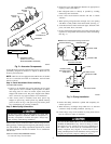
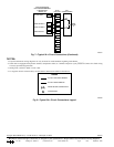
Step 6—Install Liquid-Line Filter drier (See Fig. 5)
1. Braze 5-in. connector tube to liquid service valve. Wrap filter
drier with damp cloth.
2. Braze filter drier between connector tube and liquid tube to
indoor coil. Flow arrow must point towards indoor coil.
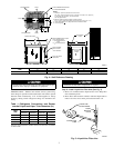
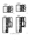
Fig. 4—Unit Reference Drawing
UNIT
SIZE
ABCDE
In. In. In. In. In.
024-060 34-15/16 30 8-3/16 4 9-3/4
A92471
AIR DISCHARGE
3
/
8
IN. DIA LIQUID
LINE CONN
FIELD CONTROL
SUPPLY CONN
7
/
8
IN. DIA HOLE
AIR DISCHARGE
AIR DISCHARGE
AIR IN
AIR IN
3
/8
"
DIA TIEDOWN KNOCKOUTS
(2) PLACES IN BASEPAN
C
L
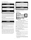
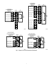
UNIT RATING
PLATE
1. Allow 30
in. (762 mm) clearance to service end of
unit, 48
in. (1219 mm) above unit, 6
in. (152 mm) on one side, 12
in. (305 mm)
on remaining side, and 24
in. (610 mm) between
units for proper airflow.
2. Minimum outdoor operating ambient in cooling mode is
55° F (12.8° C) (unless low ambient control is used) max 125° F (51.7° C).
5. Series designation is the 13th position of the unit model number.
6. Center of gravity
NOTES:
ACCESS
PANEL
FIELD POWER SUPPLY CONN
7
/
8
IN. DIA HOLE WITH
1
1
/
8
IN. DIA KNOCKOUT
AND
1
3
/
8
IN. DIA KNOCKOUT
A
C
AIR IN
E
D
B
VAPOR LINE CONN
INDIANAPOLIS IN
46206313948-401 REV A
MAX CKT-BKR
MAX HACR CKT-BKR
MAX FUSE
TYPE
MINIMUM CIRCUIT AMPS
LO
HI
DESIGN/TEST PRESSURE GAGE
FLA
HZ
PH
VOLTS AC
LRA
RLA
HZ
PH
VOLTS AC
MAX
PH
LBS
PISTON
MODEL
PROD
SERIAL
N/A
USA
N/A
CANADA
MAX OVERCURRENT PROTECTIVE DEVICE
kPa
kPa
PSI
PSI
FAN MOTOR
COMPRESSOR
SUITABLE FOR OUTDOOR USE
MIN
HZ
Kg
VOLTSPOWER SUPPLY
ID OD
FACTORY CHARGED R-22
®
®
PERMISSIBLE VOLTAGE AT UNIT
CARRIER CORP
Fig. 5—Liquid-Line Filter drier
A95509
LIQUID-LINE
FILTER-DRIER
CONNECTOR
TUBE
R
-
4
1
0
A
LIQUID
SERVICE
VALVE
3