


bearing brazing material. Consult local code requirements. Refrig-
erant tubing and indoor coil are now ready for leak testing. This
check should include all field and factory joints.
Step 5—Make Electrical Connections
Be sure field wiring complies with local and national fire, safety,
and electrical codes, and voltage to system is within limits shown
on unit rating plate. Contact local power company for correction of
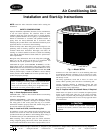
improper voltage. See unit rating plate for recommended circuit
protection device. (See Fig. 2.)
NOTE: Operation of unit on improper line voltage constitutes
abuse and could affect unit reliability. See unit rating plate.
NOTE: Use only copper wire between disconnect switch and
unit.
NOTE: Install branch circuit disconnect per NEC of adequate
size to handle unit starting current, but not larger than maximum
fuse size shown on unit rating plate. Locate disconnect within sight
from and readily accessible from unit, per Section 440-14 of NEC.
ROUTE GROUND AND POWER WIRES — Remove access
panel and control box cover to gain access to unit wiring. Extend
wires from disconnect through power wiring hole provided and
into unit control box. (See Fig. 2.) Size wires per NEC but not
smaller than minimum wire size shown in presale literature.
The cabinet must have an uninterrupted or unbroken ground
according to NEC, ANSI/NFPA 70-1993 or local codes to
minimize personal injury if an electrical fault should occur.
This may consist of electrical wire or conduit approved for
electrical ground when installed in accordance with existing
electrical codes. Failure to follow this warning could result in
an electrical shock, fire, or death.
To avoid personal injury or death, do not supply power to unit
with compressor terminal box cover removed.
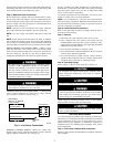
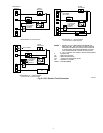
CONNECT GROUND AND POWER WIRES — Connect ground
wire to ground connection in control box for safety. Connect
power wiring to contactor as shown in Fig. 5.
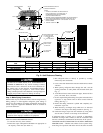
CONNECT CONTROL WIRING — Route 24-v control wires
through control wiring grommet and connect to brown and blue
pigtails supplied in unit splice box. (See Fig. 6.)
Use No. 18 AWG color-coded, insulated (35° C minimum) wire.
If thermostat is located more than 100 ft from unit (as measured
along the control voltage wires), use No. 16 AWG color-coded
wire to avoid excessive voltage drop.
Use furnace transformer, fan coil transformer, or accessory trans-
former for control power, 24-v/40va minimum.
NOTE: Use of available 24-v accessories may exceed the mini-
mum 40-va power requirement. Determine total transformer load-
ing and increase the transformer capacity or split the load with an
accessory transformer as required.
Step 6—Install Electrical Accessories
Refer to the individual instructions packaged with the kits or
accessories when installing.
Step 7—Start-up
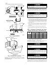
1. Fully back seat (open) liquid and vapor service valves.
2. Unit is shipped with valve stem(s) front seated and caps
installed. Replace stem caps after system is opened to refrig-
erant flow (back seated). Replace caps finger tight and tighten
additional 1/6 turn with wrench.
3. Close electrical disconnects to energize system.
4. Set room thermostat at desired temperature. Be sure set point
is below indoor ambient temperature.
5. Set room thermostat at COOL and fan switch at FAN or
AUTO, as desired. Operate unit for 15 minutes. Check system
refrigerant charge. (See Step 8—Checking Charge.)
Step 8—Checking Charge
Factory charge is shown on unit rating plate. (See Fig. 2.)
Do not disable low-pressure switch during a condenser pump
down. Compressor damage may occur if run at a negative
suction pressure.
Compressor damage may occur if system is overcharged.
Service valve gage ports are not equipped with Schrader
valves. To prevent personal injury, make sure valves are fully
back seated before removing gage port caps. Wear safety
glasses and gloves when handling refrigerant.
Adjust charge by following procedure shown on the superheat
charging tables located on unit information plate.
Do not vent refrigerant to atmosphere. Recover during system
repair or final unit disposal.
CARE AND MAINTENANCE
For continuing high performance and to minimize possible equip-
ment failure, it is essential that periodic maintenance be performed
on this equipment. Consult your servicing contractor or User’s
Manual for the proper frequency of maintenance. Frequency of
maintenance may vary depending upon geographic areas, such as
coastal applications.
Step 1—Leave User’s Manual With Homeowner
Explain system operation and maintenance procedures outlined in
User’s Manual.
Fig. 5—Line Power Connections
A91056
DISCONNECT
PER N. E. C. AND/OR
LOCAL CODES
CONTACTOR
GROUND
LUG
FIELD GROUND
WIRING
FIELD POWER
WIRING
4