


connected by 15 ft of field-supplied or factory-accessory tubing.
Check refrigerant charge for maximum efficiency. (See Step
8—Checking Charge.)
INSTALL SOLENOID VALVE IN LIQUID TUBE
Solenoid valve must be energized during evacuation for
effective evacuation.
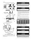
Before making liquid tube connections, install factory-supplied
solenoid valve on indoor liquid fitting. (See Fig. 4.) Be sure to use
flare adapter supplied with the indoor coil when making connec-
tions.
If a field-supplied control power source is needed when
adding solenoid, wiring must comply with local codes and
NEC requirements.
1. Remove coil liquid connection cap and discard.
2. Mount solenoid valve on liquid tube, making sure valve flow
arrow points toward indoor coil. Mount valve in any position
except valve body at top and electric coil at bottom. (See Fig.
4.) The solenoid valve is to be installed a maximum of 24 in.
from indoor coil.
3. Braze valve onto end of liquid tube using silver bearing or
non-silver bearing brazing material. Consult local code re-
quirements.
4. Braze flare adapter onto outlet end of the solenoid valve.
5. Wire solenoid coil into system control circuit as shown in Fig.
6.
Table 1—Refrigerant Connections and Recom-
mended Liquid and Vapor Tube Diameters (In.)
UNIT
SIZE
LIQUID VAPOR
Connect
Diameter
Tube
Diameter
Connect
Diameter
Tube
Diameter
018, 024 3/8 3/8 5/8 5/8
030, 036 3/8 3/8 3/4 3/4
042, 048 3/8 3/8 7/8 7/8
060 3/8 3/8 7/8 1-1/8
Notes: 1. Tube diameters are for lengths up to 50 ft. For tubing lengths greater
than 50 ft, consult Long-Line Application Guideline.
2. Do not apply capillary-tube indoor coils to these units.
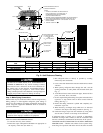
REFRIGERANT TUBING — Connect tubing to fittings on out-
door unit vapor and liquid service valves. (See Fig. 2.)
A brazing shield MUST be used when tubing sets are being
brazed to the service valves to prevent damage to the painted
unit surface.
Relieve pressure and recover all refrigerant before system
repair or final unit disposal to avoid personal injury or death.
Use all service ports and open all flow control devices,
including solenoid valves.
To avoid valve damage while brazing, service valves must be
wrapped with a heat-sinking material such as a wet cloth.
SWEAT CONNECTION — Use refrigerant grade tubing. Service
valves are closed from factory and ready for brazing. After
wrapping the service valve with a wet cloth, the tubing set can be
brazed to the service valve using either silver bearing or non-silver
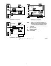
Fig. 3—Piping Installation
A92469
OUTDOOR WALL
CAULK
INDOOR WALL
LIQUID LINE
VAPOR LINE
INSULATION
JOIST
INSULATION
HANGER STRAP
(AROUND VAPOR
LINE ONLY)
VAPOR LINE
LIQUID
LINE
THROUGH THE WALL
SUSPENSION
1″
MIN
NOTE:
AVOID CONTACT BETWEEN TUBING AND STRUCTURE
Fig. 4—Solenoid Valve Installation
A87044
ELECTRICAL JUNCTION
ELECTRICAL COIL
VALVE
FLOW ARROW
STRAIGHT
3
/
8
IN. STUD
NOTE:System flow direction
must match arrow on
bottom of body.
3