


DO NOT BURY MORE THAN 36 IN. OF REFRIGERANT
TUBING IN GROUND. If any section of tubing is buried,
there must be a 6-in. vertical rise to the valve connections on
the outdoor unit. If more than the recommended length is
buried, refrigerant may migrate to cooler buried section
during extended periods of unit shutdown, causing refrigerant
slugging and possible compressor damage at start-up.
Step 4—Make Piping Connections
Outdoor units may be connected to indoor sections using accessory
tubing package or field−supplied refrigerant grade tubing of
correct size and condition. For tubing requirements beyond 50 ft,
consult Long-Line Application Guideline which is available at
your local distributor.
In some cases noise in the living area has been traced to gas
pulsations from improper installation of equipment.
INSTALLATION RECOMMENDATIONS
1. Locate the unit away from windows.
2. Ensure that vapor and liquid line diameters are appropriate to
the capacity of the unit. (See Table 1.)
3. Run refrigerant tubes as directly as possible by avoiding
unnecessary turns and bends.
4. Leave some slack between the structure and the unit to absorb
vibration.
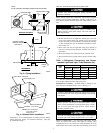
5. When passing refrigerant tubes through the wall, seal the
opening with RTV or other pliable silicon-based caulk. (See
Fig. 3.)
6. Avoid direct lineset contact with water pipes, ductwork, floor
joists, wall studs, floors, and walls.
7. Do not suspend refrigerant tubing from joists and studs with a
rigid wire or strap which comes in direct contact with the
tubing. (See Fig. 3.)
8. Ensure that tubing insulation is pliable and completely sur-
rounds the vapor line.
9. When necessary, use hangar straps which are 1 in. wide and
conform to the shape of the tubing insulation. (See Fig. 3.)
10. Isolate the hangar straps from the insulation by using metal
sleeves bent to conform to the shape of the insulation.
If refrigerant tubes or indoor coil is exposed to atmospheric
conditions for longer than 5 minutes, it must be evacuated to 500
microns to eliminate contamination and moisture in the system.
OUTDOOR UNITS CONNECTED TO FACTORY-APPROVED
INDOOR UNITS — Outdoor unit contains correct system refrig-
erant charge for operation with indoor unit of the same size when
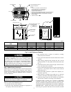
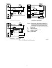
Fig. 2—Unit Reference Drawing
UNIT
SIZE
A B C D E
In. In. In. In. In.
018 27-1/2 22-1/2 8-3/16 2-13/16 6-15/16
024-048 34-15/16 30 8-3/16 4 9-3/4
060 (301 Series) 45 38-5/8 8-9/16 5-15/16 11-13/16
060 (311 Series) 34-15/16 30 8-3/16 4 9-3/4
A92471
AIR DISCHARGE
3
/
8
″ DIA LIQUID
LINE CONN
FIELD CONTROL
SUPPLY CONN
7
/
8
″ DIA HOLE
AIR DISCHARGE
AIR DISCHARGE
AIR IN
AIR IN
3
/8
"
DIA TIEDOWN KNOCKOUTS
(2) PLACES IN BASEPAN
C
L
UNIT RATING
PLATE
1. ALLOW 30″ CLEARANCE TO SERVICE END OF
UNIT, 48″ ABOVE UNIT, 6″ ON ONE SIDE, 12″
ON REMAINING SIDE, AND 24″ BETWEEN
UNITS FOR PROPER AIRFLOW.
2. MINIMUM OUTDOOR OPERATING AMBIENT IN COOLING MODE IS
55° F (UNLESS LOW AMBIENT CONTROL IS USED) MAX 125° F.
5. SERIES DESIGNATION IS THE 13TH POSITION OF THE UNIT
MODEL NUMBER.
6. CENTER OF GRAVITY
NOTES:
ACCESS
PANEL
FIELD POWER SUPPLY CONN
7
/
8
″ DIA HOLE WITH
1
1
/
8
″ DIA KNOCKOUT
AND
1
3
/
8
″ DIA KNOCKOUT
A
C
AIR IN
E
D
B
VAPOR LINE CONN
INDIANAPOLIS IN
46206313948-401 REV A
MAX CKT-BKR
MAX HACR CKT-BKR
MAX FUSE
TYPE
MINIMUM CIRCUIT AMPS
LO
HI
DESIGN/TEST PRESSURE GAGE
FLA
HZ
PH
VOLTS AC
LRA
RLA
HZ
PH
VOLTS AC
MAX
PH
LBS
PISTON
MODEL
PROD
SERIAL
N/A
USA
N/A
CANADA
MAX OVERCURRENT PROTECTIVE DEVICE
kPa
kPa
PSI
PSI
FAN MOTOR
COMPRESSOR
SUITABLE FOR OUTDOOR USE
MIN
HZ
Kg
VOLTSPOWER SUPPLY
ID OD
FACTORY CHARGED R-22
®
®
PERMISSIBLE VOLTAGE AT UNIT
CARRIER CORP
2