


9
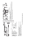
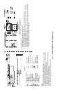
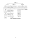
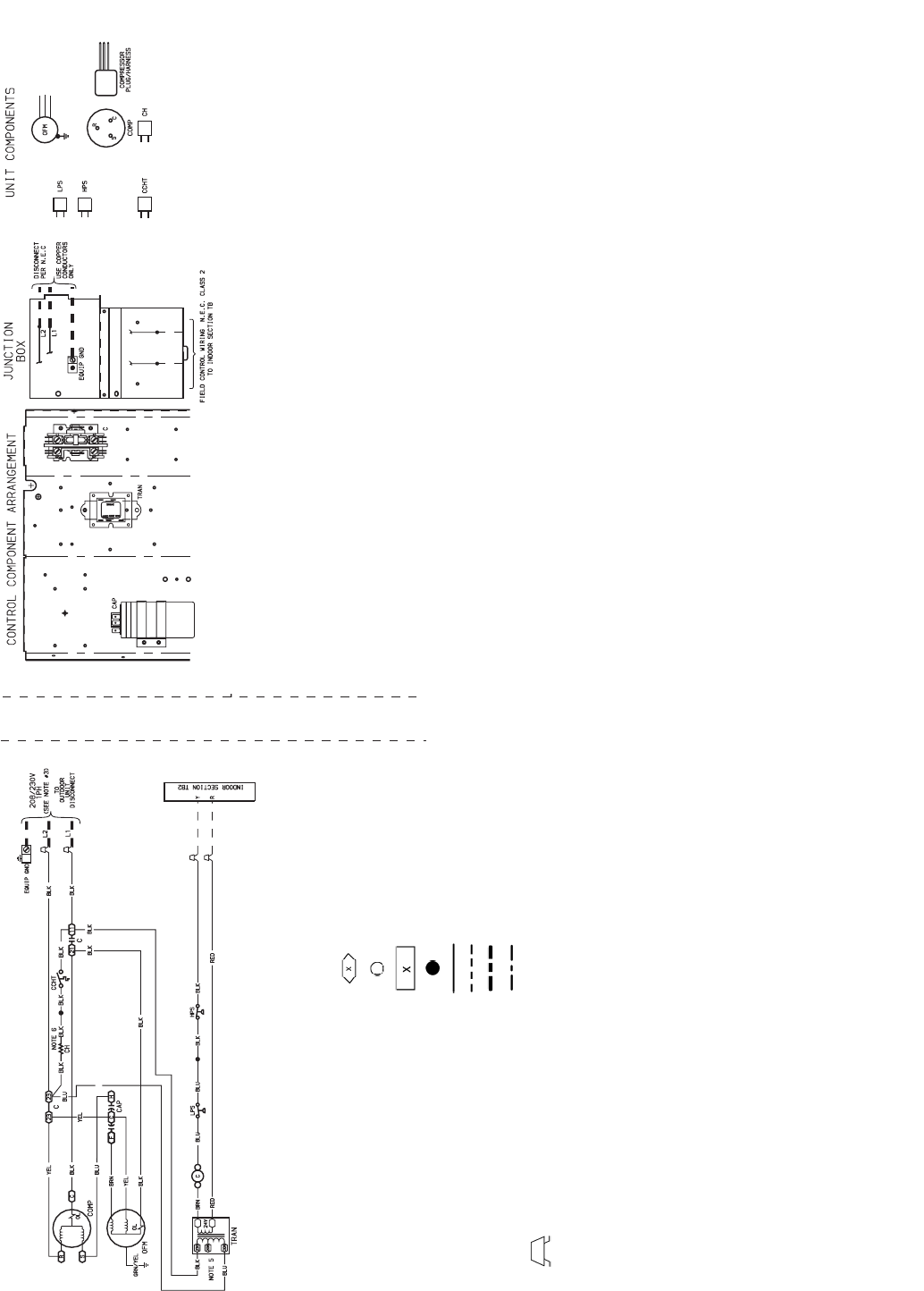
LEGEND
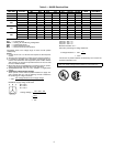
NOTES:
1. Compressor and fan motors are thermally protected.
2. Wire in accordance with National Electrical Code (NEC) and local codes. Replace
any original wires with 90° C wire or its equivalent.
3. Use minimum 60° C wire for field power wiring.
4. Transformer has internal 4.5A thermal fuse on the primary side.
5. Transformer factory wired for 230 v. For 208 v move black wire to 208 volt tap on
transformer.
6. Crankcase heater and thermostat used on selected models only.
C—Contactor, Compressor
CAP — Capacitor
CCHT — Crankcase Heater Thermostat
CH — Crankcase Heater
COMP — Compressor Motor
EQUIP— Equipment
GND — Ground
HPS — High-Pressure Switch
LPS — Low-Pressure Switch
OFM — Outdoor-Fan Motor
OL — Overload
TB — Terminal Board
TRAN — Transformer
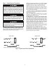
Splice (Field)
Terminal (Marked)
Terminal (Unmarked)
Terminal Block
Splice
Factory Wiring
Field Control Wiring
Field Power Wiring
Optional or Accessory Wire
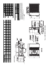
Fig. 6 — 38HDF018-036 Typical Wiring Schematic
38HDF OPERATION SEQUENCE
CALL FOR COOLING:
1. Control voltage from transformer to thermostat (24 v).
2. At thermostat 24 v is switched to “G” and “Y.”
3. 24 v from thermostat “G” energizes fan relay at indoor fan coil unit and indoor-fan motor runs.
4. 24 v from thermostat “Y” energizes the contactor coil and the compressor and outdoor-fan motor will both
run.
6. If the internal protection of the compressor or LPS or HPS open, the 24 v to contactor coil will be inter-
rupted. The compressor and outdoor-fan motor will stop.