


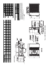
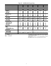
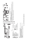
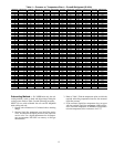
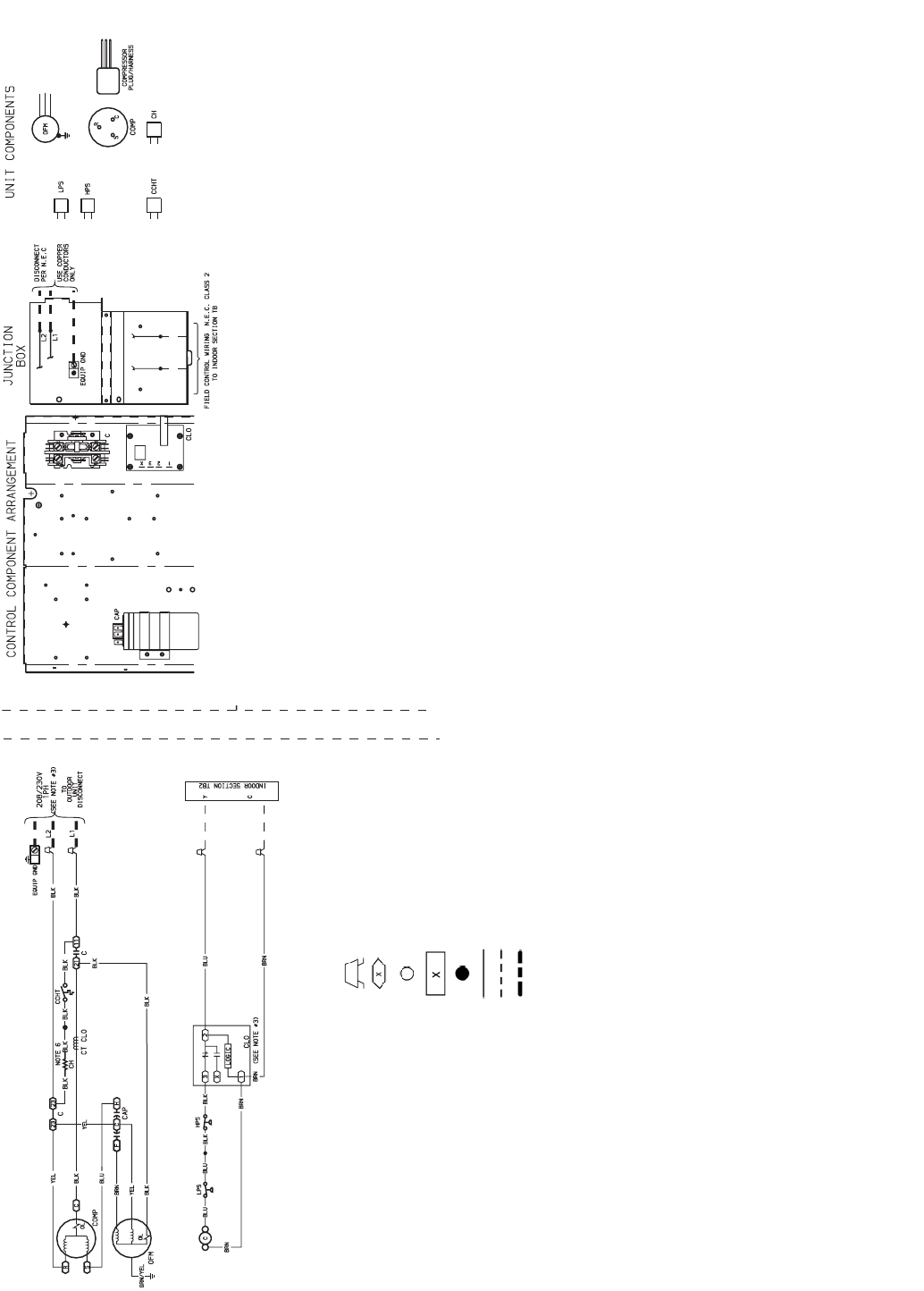
10
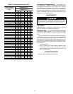
LEGEND
NOTES:
1. Compressor and fan motors are thermally protected.
2. Wire in accordance with National Electrical Code (NEC) and local codes. Replace
any original wires with 90° C wire or its equivalent.
3. The CLO locks out the COMP to prevent short cycling on COMP overloads and
safety devices. Before replacing CLO check these devices.
4. If indoor section has a transformer with a grounded secondary, connect the
grounded side to “C” on the low voltage board.
5. Use minimum 60° C wire for field power wiring.
6. Crankcase heater and thermostat used on selected models only.
C—Contactor, Compressor
CAP — Capacitor
CCHT — Crankcase Heater
Thermostat
CH — Crankcase Heater
CLO — Compressor Lockout
COMP — Compressor Motor
CT — Current Transformer
EQUIP — Equipment
GND — Ground
HPS — High-Pressure Switch
LPS — Low-Pressure Switch
OFM — Outdoor-Fan Motor
OL — Overload
TB — Terminal Board
Splice (Field)
Terminal (Marked)
Terminal (Unmarked)
Terminal Block
Splice
Factory Wiring
Field Control Wiring
Field Power Wiring
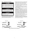
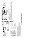
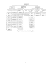
38HDR OPERATION SEQUENCE
CALL FOR COOLING:
1. Control voltage from transformer to thermostat (24 v).
2. At thermostat 24 v is switched to “G” and “Y.”
3. 24 v from thermostat “G” energizes fan relay at indoor fan coil and indoor-fan motor runs.
4. 24 v from thermostat “Y” energizes the logic in the CLO, and the contactor coil, both at the outdoor unit.
Compressor and outdoor-fan motor run.
6. If the internal protector of the compressor, HPS, or LPS open, the 24 v to the contactor coil will be inter-
rupted, the compressor and outdoor-fan motor will stop, and the CLO will keep the circuit open until reset
by stopping and restarting the 24 v power at the thermostat.
Fig. 7 — 38HDR018-060 Typical Wiring Schematic