


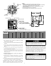
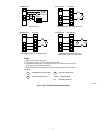

CONNECT CONTROL WIRING — Route 24-v control wires
through control wiring grommet and connect to brown and blue
pigtails supplied in unit splice box. (See Fig. 5.)
Use furnace transformer, fan-coil transformer, or accessory trans-
former for control power, 24-v/40va minimum.
NOTE: Use of available 24-v accessories may exceed the mini-
mum 40-va power requirement. Determine total transformer load-
ing and increase the transformer capacity or split the load with an
accessory transformer as required.
Step 6—Compressor Crankcase Heat
When equipped with a crankcase heater, energize heater a mini-
mum of 24 hrs before starting unit. To energize heater only, set
thermostat to OFF position and close electrical disconnect to
outdoor unit.
A crankcase heater is required if the refrigerant tubing is longer
than 50 ft (15.24m).
Step 7—Install Electrical Accessories, If Any
Refer to the individual instructions packaged with the kit or
accessory when installing.
Step 8—Start-Up and Check Charge
To prevent compressor damage or personal injury, observe
the following:
• Do not overcharge system with refrigerant.
• Do not operate unit in a vacuum or at negative pressure.
• Do not disable low-pressure switch.
In scroll compressor applications:
• Dome temperatures may be hot.
• In 3 phase application, incorrect phasing will cause reverse
rotation, resulting in elevated noise levels, equalized pres-
sures and reduced current draw. Correct by reversing power
connection L1 and L2 on contactor.
To prevent personal injury wear safety glasses, protective
clothing, and gloves when handling refrigerant and observe
the following:
• Back seating service valves are not equipped with Schrader
valves. Fully back seat (counter clockwise) valve stem before
removing gage port cap.
• Front seating service valves are equipped with Schrader
valves.
Do not vent refrigerant to atmosphere. Recover during system
repair or final unit disposal.
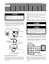
1. Fully back seat (open) liquid and vapor tube service valves.
2. Unit is shipped with valve stem(s) front seated and caps
installed. Replace stem caps after system is opened to refrig-
erant flow (back seated). Replace caps finger-tight and tighten
additional 1/6 turn with wrench.
3. Close electrical disconnects to energize system.
4. Set room thermostat at desired temperature. Be sure set point
is below indoor ambient temperature.
5. Set room thermostat at COOL and fan switch at FAN or
AUTO, as desired. Operate unit for 15 minutes. Check system
refrigerant charge.
6. Factory charge is shown on unit rating label. Adjust charge by
following procedure shown on charging tables located on unit.
Step 9—Leave User’s Manual with Owner
For continued high performance and to minimize possible equip-
ment failure, periodic maintenance MUST be performed on this
equipment.
Leave User’s Manual with owner. Explain system operation and
periodic maintenance requirements outlined in manual. Frequency
of maintenance may vary depending on geographic areas, such as
coastal applications which require more frequent maintenance.
4