


To prevent damage to unit or service valves observe the
following:
• Use a brazing shield.
• Wrap service valves with wet cloth or use a heat sink
material.
SWEAT CONNECTION — Use refrigerant grade tubing. Service
valves are closed from factory and ready for brazing. After
wrapping the service valve with a wet cloth, the tubing set can be
brazed to the service valve using either silver bearing or non-silver
bearing brazing material. Consult local code requirements. Refrig-
erant tubing and indoor coil are now ready for leak testing. This
check should include all field and factory joints.
Step 5—Make Electrical Connections
Be sure field wiring complies with local and national fire, safety,
and electrical codes, and voltage to system is within limits shown
on unit rating label. Contact local power company for correction of
improper voltage. See unit rating label for recommended circuit
protection device.
NOTE: Operation of unit on improper line voltage constitutes
abuse and could affect unit reliability. See unit rating label. Do not
install unit in system where voltage or phase imbalance may
fluctuate above or below permissible limits.
NOTE: Use copper wire only between disconnect switch and
unit.
NOTE: Install branch circuit disconnect per local codes of
adequate size to handle unit starting current. Locate disconnect
within sight from and readily accessible from unit per local codes.
To avoid personal injury or death, do not supply power to unit
with compressor terminal box cover removed.
The unit cabinet must have an uninterrupted or unbroken
ground to minimize personal injury if an electrical fault
should occur. The ground may consist of electrical wire or
metal conduit when installed in accordance with existing
electrical codes. Failure to follow this warning can result in an
electric shock, fire, or death.
ROUTE GROUND AND POWER WIRES — Remove access
panel and control box cover to gain access to unit wiring. Extend
wires from disconnect through power wiring hole provided and
into unit control box. (See Fig. 2.) Size wires per local codes, but
not smaller than minimum wire size shown on unit rating label.
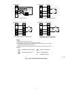
CONNECT GROUND AND POWER WIRES — Connect ground
wire to ground connection in control box for safety. Connect
power wiring to contactor as shown in Fig. 4.
NOTE: Use No. 18 AWG (American Wire Gage) color-coded,
insulated (35° C minimum) wire. If thermostat is located more than
100 ft (30.5m) from unit as measured along the control voltage
wires, use No. 16 AWG color-coded wires to avoid excessive
voltage drop.
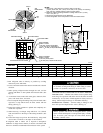
Table 1—Refrigerant Connections and Recommended Liquid and Vapor Tube Diameters
UNIT SIZE
LIQUID VAPOR
Connection Dia. Tube Dia. Connection Dia. Tube Dia.
In. mm In. mm In. mm In. mm
018, 024 3/8 9.53 3/8 9.53 5/8 15.88 5/8 15.88
036 3/8 9.53 3/8 9.53 3/4 19.05 3/4 19.05
048 3/8 9.53 3/8 9.53 7/8 22.23 7/8 22.23
060 3/8 9.53 3/8 9.53 7/8 22.23 1-1/8 28.58
1. Tube diameters are for lengths up to 50 ft (15.24m). For tube sets over 50 ft (15.24m), consult Long-Line Application Guideline.
2. Do not apply capillary tube indoor coils to these units.
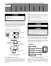
Fig. 3—Piping Installation
A94330
INSULATION
VAPOR TUBE
LIQUID TUBE
OUTDOOR WALL INDOOR WALL
LIQUID TUBE
VAPOR TUBE
INSULATION
CAULK
Avoid contact between tubing and structure.NOTE:
THROUGH THE WALL
HANGER STRAP
(AROUND VAPOR
TUBE ONLY)
JOIST
1″ MIN
(25 mm)
SUSPENSION
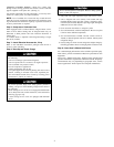
Fig. 4—Line Power Connections
A94025
DISCONNECT
PER N.E.C. AND/OR
LOCAL CODES
CONTACTOR
GROUND
LUG
FIELD GROUND
WIRING
FIELD POWER
WIRING
BLUE
3 PHASE ONLY
3