


3. Run refrigerant tubes as directly as possible by avoiding
unnecessary turns and bends.
4. Leave some slack between the structure and the unit to absorb
vibration.
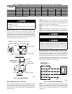
5. When passing refrigerant tubes through the wall, seal the
opening with RTV or other pliable silicon-based caulk. (See
Fig. 3.)
6. Avoid direct lineset contact with water pipes, ductwork, floor
joists, wall studs, floors, and walls.
7. Do not suspend refrigerant tubing from joists and studs with a
rigid wire or strap which comes in direct contact with the
tubing. (See Fig. 3.)
8. Ensure that tubing insulation is pliable and completely sur-
rounds the vapor tube.
9. When necessary, use hangar straps which are 1 in. (25mm)
wide and conform to the shape of the tubing insulation. (See
Fig. 3.)
10. Isolate the hangar straps from the insulation by using metal
sleeves bent to conform to the shape of the insulation.
If refrigerant tubes or indoor coil is exposed to atmospheric
conditions for longer than 5 minutes, it must be evacuated to 500
microns to eliminate contamination and moisture in the system.
To prevent compressor damage DO NOT bury more than 36
in. (914mm) of refrigerant tubing. If ANY tubing is buried,
provide 6 in. (152mm) vertical rise at service valve.
OUTDOOR UNITS CONNECTED TO FACTORY-APPROVED
INDOOR UNITS — Outdoor unit contains correct system refrig-
erant charge for operation with indoor unit of the same size when
connected by 15 ft (4.55m) of field-supplied or factory-accessory
tubing. Check refrigerant charge for maximum efficiency.
REFRIGERANT TUBING — Connect tubing to fittings on out-
door unit vapor and liquid service valves. (See Fig. 2.)
Relieve pressure and recover all refrigerant before system
repair or final unit disposal to avoid personal injury or death.
Use all service ports and open all flow-control devices,
including solenoid valves.
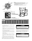
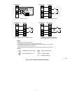
Fig. 2—Unit Reference Drawing
UNIT SIZE
A/B C D E F
In. mm In. mm In. mm In. mm In. mm
018 18 457.2 3 76.2 15 381.0 10-3/16 258.8 5/8 15.9
024 22-1/2 571.5 3-11/16 93.6 18-1/8 460.4 14-3/8 365.1 5/8 15.9
036 22-1/2 571.5 3-11/16 93.6 18-1/8 460.4 14-3/8 365.1 3/4 19.1
048, 060 30 762.0 6-1/2 165.1 23-1/2 596.9 20 508.0 7/8 22.2
A91173
AIR DISCHARGE
3
⁄
8
IN. DIA (9.53) LIQUID LINE CONN
FIELD CONTROL
SUPPLY CONN
7
⁄
8
IN. DIA (22.22) HOLE
AIR
DISCHARGE
AIR
DISCHARGE
AIR IN
AIR IN
1. Allow 30 in. (762) clearance to service sides of unit, 48 in.
(1219.2) above unit, 6 in. (152.4) on one side, 12 in. (304.8) on remaining
side, and 24 in. (609.6) between units for proper airflow.
2. Minimum outdoor operating ambient in cooling mode is 55 F (12.8 C),
max 115 F (46.1 C).
3. Dimensions in parenthesis are in millimeters.
4. Series designation is the 13th position of the unit model number.
NOTES:
FIELD POWER
SUPPLY CONN
7
⁄
8
IN. DIA (22.22) HOLE WITH
1
1
⁄
8
IN. DIA (28.57) KNOCKOUT
AND 1
3
⁄
8
IN. DIA (34.92) KNOCKOUT
AIR IN
AIR
IN
AIR DISCHARGE
F DIA SUCTION LINE CONN
RATING LABEL
A
B
E
D
C
2