


38CKB—50 Hz
Air Conditioning Unit
Installation and Start-Up Instructions
NOTE: Read the entire instruction manual before starting the
installation.
SAFETY CONSIDERATIONS
Improper installation, adjustment, alteration, service, maintenance,
or use can cause explosion, fire, electrical shock, or other
conditions which may cause death, personal injury, or property
damage. Consult a qualified installer, service agency, or your
distributor or branch for information or assistance. The qualified
installer or agency must use factory-authorized kits or accessories
when modifying this product. Refer to the individual instructions
packaged with the kits or accessories when installing.
Follow all safety codes. Wear safety glasses, protective clothing,
and work gloves. Use quenching cloth for brazing operations.
Have fire extinguisher available. Read these instructions thor-
oughly and follow all warnings or cautions included in literature
and attached to the unit. Consult local building codes and national
electric codes for special requirements.
Recognize safety information. This is the safety-alert symbol
.
When you see this symbol on the unit and in instructions or
manuals, be alert to the potential for personal injury.
Understand the signal word DANGER, WARNING, or CAU-
TION. These words are used with the safety-alert symbol. DAN-
GER identifies the most serious hazards which will result in severe
personal injury or death. WARNING signifies hazards which
could result in personal injury or death. CAUTION is used to
identify unsafe practices which would result in minor personal
injury or product and property damage.
Before installing, modifying, or servicing system, main elec-
trical disconnect switch must be in the OFF position. There
may be more than 1 disconnect switch. Lock out and tag
switch with a suitable warning label. Electrical shock can
cause personal injury or death.
INSTALLATION
Step 1—Check Equipment and Jobsite
UNPACK UNIT — Move to final location. Remove carton taking
care not to damage unit.
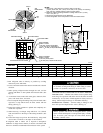
INSPECT EQUIPMENT — File claim with shipping company
prior to installation if shipment is damaged or incomplete. Locate
unit rating label on unit service panel. (See Fig. 2.) It contains
information needed to properly install unit. Check rating label to
be sure unit matches job specifications.
Step 2—Install on a Solid, Level Mounting Pad
If conditions or local codes require the unit be attached to pad,
tiedown bolts should be used and fastened through knockouts
provided in unit base pan. Refer to unit mounting pattern in Fig. 2
to determine base pan size and knockout hole location.
When installing, allow sufficient space for airflow clearance,
wiring, refrigerant piping, and service. Allow 30-in. (762mm)
clearance to service end of unit and 48 in. (1219mm) above unit.
For proper airflow, a 6-in. (152mm) clearance on 1 side of unit and
12 in. (305mm) on all remaining sides must be maintained.
Maintain a distance of 24 in. (610mm) between air conditioners.
Position so water, snow, or ice from roof or eaves cannot fall
directly on unit.
On rooftop applications, locate unit 6 in. (152mm) above roof
surface. Where possible, place unit above a load-bearing wall.
Arrange supporting members to adequately support unit and
minimize transmission of vibration to building. Consult local
codes governing rooftop applications.
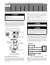
Step 3—Replace Indoor AccuRater® Piston, if Required
Check indoor coil piston to see if it matches the required piston
shown on unit rating label. If it does not match, replace indoor coil
piston with piston shipped with this unit. The piston shipped with
outdoor unit is correct for any approved indoor coil combination.
Remove indoor coil piston if unit is to be installed on system
with a TXV metering device.
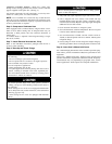
Step 4—Make Piping Connections
Outdoor units may be connected to indoor sections using accessory
tubing package or field-supplied refrigerant grade tubing of correct
size and condition. For tubing requirements beyond 50 ft (15.24m),
consult Long-Line Application Guideline which is available at
your local distributor.
NOTE: In some cases, noise in the living area has been traced to
gas pulsations from improper installation of equipment.
INSTALLATION RECOMMENDATIONS
1. Locate the unit away from windows.
2. Ensure that vapor and liquid tube diameters are appropriate to
the capacity of the unit. (See Table 1.)
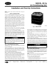
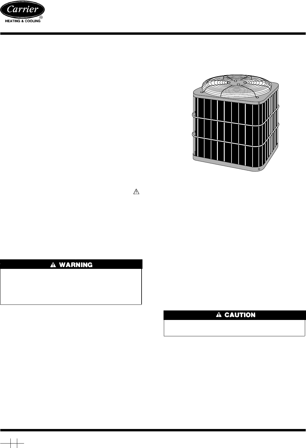
Fig. 1—Model 38CKB
A94356
Manufacturer reserves the right to discontinue, or change at any time, specifications or designs without notice and without incurring obligations.
Book 1 4
Tab 3a 2a
PC 101 Catalog No. 013-862 Printed in U.S.A. Form 38CKB-C1SI Pg 1 12-94 Replaces: New