


4. Set room thermostat to desired temperature. Be sure set point
is below indoor-ambient temperature.
5. Set room thermostat to HEAT or COOL and fan control to ON
or AUTO mode, as desired. Operate unit for 15 minutes.
Check system-refrigerant charge.
SEQUENCE OF OPERATION
NOTE: Defrost-control board may be equipped with 5-minute
lockout timer that may be initiated upon any interruption of power.
With power supplied to indoor and outdoor units, transformer is
energized.
COOLING
On a call for cooling, thermostat makes circuits R-O, R-Y, and
R-G. Circuit R-O energizes reversing valve, switching it to cooling
position. Circuit R-Y energizes contactor, starting outdoor-fan
motor and compressor circuit. R-G energizes indoor unit-blower
relay, starting indoor-blower motor on high speed.
When thermostat is satisfied, its contacts open, de-energizing the
contactor and blower relay. Compressor and motors should stop.
NOTE: If indoor unit is equipped with a time-delay relay circuit,
the blower runs an additional 90 sec to increase system efficiency.
HEATING
On a call for heating, thermostat makes circuits R-Y and R-G.
Circuit R-Y energizes contactor, starting outdoor-fan motor and
compressor. Circuit R-G energizes indoor-blower relay, starting
blower motor on high speed.
Should temperature continue to fall, R-W2 is made through
second-stage room-thermostat bulb. Circuit R-W2 energizes a
relay, bringing on first bank of supplemental electric heat and
providing electrical potential to second heater relay (if used). If
outdoor temperature falls below setting of outdoor thermostat
(field-installed option), contacts close to complete circuit and bring
on second bank of supplemental electric heat.
When thermostat is satisfied, its contacts open, de-energizing
contactor and relay. All heaters and motors should stop.
DEFROST
The defrost control is a time/temperature control which includes a
field-selectable (quick-connects located at board edge) time period
between defrost cycles (30, 60, or 90 minutes), factory set at 90
minutes.
The electronic timer and defrost cycle start only when contactor is
energized and defrost thermostat is closed.
Defrost mode is identical to cooling mode except that outdoor-fan
motor stops and second-stage heat is turned on to continue
warming conditioned space.
To initiate defrost, the defrost thermostat must be closed. This can
be accomplished as follows:
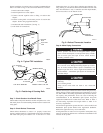
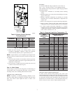
1. Turn off power to outdoor unit.
2. Disconnect outdoor-fan motor lead from OF2 on control
board. (See Fig. 10.) Tape lead to prevent grounding.
3. Restart unit in heating mode, allowing frost to accumulate on
outdoor coil.
4. After a few minutes in heating mode, liquid-line temperature
should drop below closing point of defrost thermostat (ap-
proximately 30°F).
5. Short between speed-up terminals with a flat-blade screw-
driver. (See Fig. 10.) This reduces the timing sequence to
1/256th of original time. (See Table 3.)
24 VAC HOT
R
C
W2
Y
G
R
C
RVS COOLING
C
W2
HP THERMOSTAT
TYPICAL
FAN COIL
HEAT
PUMP
G
O
E
W2
E
W3
R
Y
24 VAC COM
HEAT STAGE 2
COOL/HEAT
STAGE 1
INDOOR FAN
EMERGENCY
HEAT
O
*
*
*
IF AVAILABLE
*
A02325
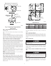
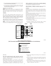
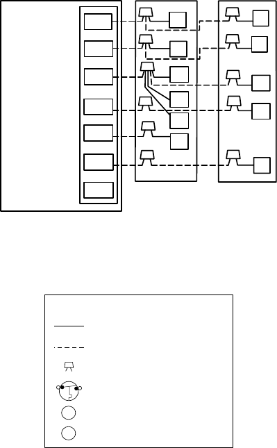
Fig. 9—Generic Wiring Diagram
(See Thermostat Installation Instructions for wiring specific unit combinations.)
A97413
LEGEND
24-V FACTORY WIRING
24-V FIELD WIRING
FIELD SPLICE CONNECTION
OUTDOOR THERMOSTAT
EMERGENCY HEAT RELAY
SUPPLEMENTAL HEAT RELAY
SHR
EHR
ODT
6