


OUTDOOR UNIT CONNECTED TO FACTORY APPROVED
INDOOR UNIT
Outdoor unit contains correct system refrigerant charge for opera-
tion with indoor unit of same size when connected by 15 ft of
field-supplied or factory accessory tubing. Check refrigerant
charge for maximum efficiency.
REFRIGERANT TUBING
Connect tubing to fittings on outdoor unit vapor- and liquid-
service valves. (See Table 1.) Use refrigerant grade tubing.
SWEAT CONNECTION
To avoid valve damage while brazing, service valves must be
wrapped in a heat sink material such as a wet cloth.
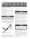
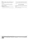
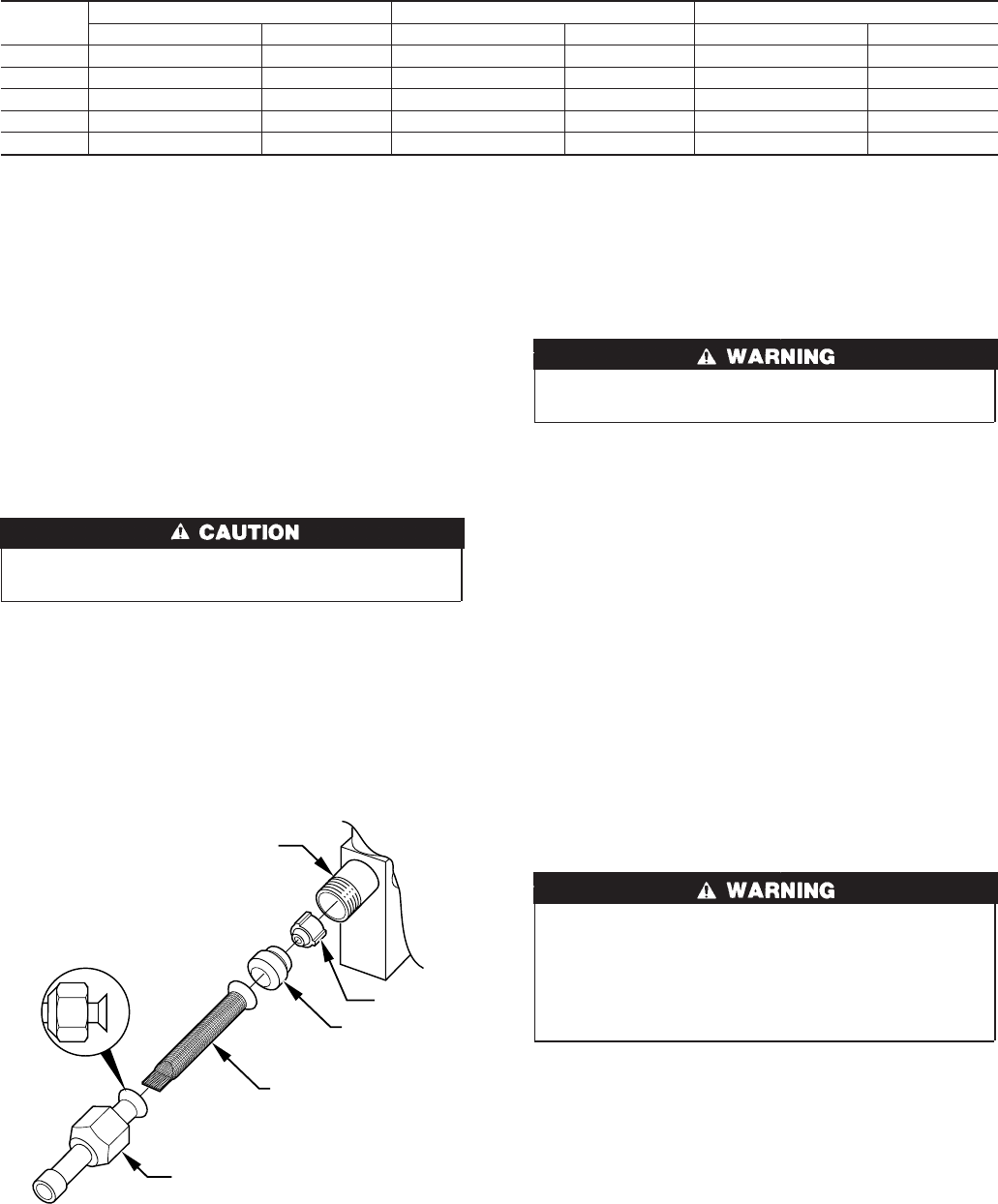
Remove plastic retainer holding outdoor piston in liquid service
valve and connect sweat/flare adapter provided to valve. (See Fig.
7.) Connect refrigerant tubing to fittings on outdoor unit vapor-
and liquid-service valves. Service valves are closed from factory
and ready for brazing. After wrapping service valve with a wet
cloth, tubing set can be brazed to service valve using either silver
bearing or non-silver bearing brazing material. Consult local code
requirements. Refrigerant tubing and indoor coil are now ready for
leak testing. This check should include all field and factory joints.
IMPORTANT: Check to be certain factory tubing on both indoor
and outdoor unit has not shifted during shipment. Ensure tubes are
not rubbing against each other or any sheet metal. Pay close
attention to feeder tubes, making sure wire ties on feeder tubes are
secure and tight.
Step 10—Make Electrical Connections
To avoid personal injury or death, do not supply power to unit
with compressor terminal box cover removed.
Be sure field wiring complies with local and national fire, safety,
and electrical codes, and voltage to system is within limits shown
on unit rating plate. Contact local power company for correction of
improper voltage. See unit rating plate for recommended circuit-
protection device.
NOTE: Operation of unit on improper line voltage constitutes
abuse and could affect unit reliability. See unit rating plate. Do not
install unit in system where voltage may fluctuate above or below
permissible limits.
NOTE: Use copper wire only between disconnect switch and
unit.
NOTE: Install branch circuit disconnect of adequate size per
NEC to handle unit starting current. Locate disconnect within sight
from and readily accessible from unit, per Section 440-14 of NEC.
ROUTE GROUND AND POWER WIRES
Remove access panel to gain access to unit wiring. Extend wires
from disconnect through power wiring hole provided and into unit
control box.
The unit cabinet must have an uninterrupted or unbroken
ground to minimize personal injury if an electrical fault
should occur. The ground may consist of electrical wire or
metal conduit when installed in accordance with existing
electrical codes. Failure to follow this warning can result in an
electric shock, fire, or death.
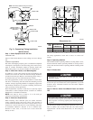
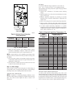
CONNECT GROUND AND POWER WIRES
Connect ground wire to ground connection in control box for
safety. Connect power wiring to contactor as shown in Fig. 8.
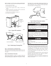
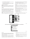
CONNECT CONTROL WIRING
Route 24v control wires through control wiring grommet and
connect leads to control wiring. See Thermostat Installation
Instructions for wiring specific unit combinations. (See Fig. 9.)
Use No. 18 AWG color coded, insulated (35°C minimum) wire. If
thermostat is located more than 100 ft from unit, as measured
along the control voltage wires, use No. 16 AWG color coded wire
to avoid excessive voltage drop.
All wiring must be NEC Class 1 and must be separated from
incoming power leads.
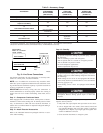
Table 1—Refrigerant Connections And Recommended Liquid- And Vapor-Tube Diameters (In.)
UNIT
SIZE
LIQUID VAPOR VAPOR (LONG LINE)
Connection Diameter Tube Diameter Connection Diameter Tube Diameter Connection Diameter Tube Diameter
018 3/8 3/8 5/8 5/8 5/8 3/4
024 3/8 3/8 3/4 3/4 3/4 3/4
030, 036 3/8 3/8 3/4 3/4 3/4 7/8
042 3/8 3/8 7/8 7/8 7/8 1-1/8
048, 060 3/8 3/8 7/8 1-1/8 7/8 1-1/8
NOTES:
1. Tube diameters are for lengths up to 50 ft. For tubing lengths greater than 50 ft horizontal, or greater than 20 ft vertical differential, consult the Application Guideline
and Service Manual — Air Conditioners and Heat Pumps.
2. Do not apply capillary tube indoor coils to these units.
Fig. 7—Liquid-Service Valve
A97512
PISTON BODY
PISTON
PISTON
RETAINER
SWEAT/FLARE ADAPTER
STRAINER
4