


Use furnace transformer, fan coil transformer, or accessory trans-
former for control power, 24v/40va minimum.
NOTE: Use of available 24v accessories may exceed the mini-
mum 40va power requirement. Determine total transformer load-
ing and increase the transformer capacity or split the load with an
accessory transformer as required.
IMPORTANT: Check factory wiring and wire connections to
ensure terminations are secured properly. Check wire routing to
ensure wires are not in contact with tubing, sheet metal, and so
forth.
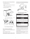
Step 11—Compressor Crankcase Heater
When equipped with a crankcase heater, furnish power to heater a
minimum of 24 hr before starting unit. To furnish power to heater
only, set thermostat to OFF and close electrical disconnect to
outdoor unit. A crankcase heater is required if refrigerant tubing is
longer than 50 ft.
Step 12—Install Electrical Accessories
Refer to the individual instructions packaged with kits or acces-
sories when installing.
Step 13—Start-Up
To prevent compressor damage or personal injury, observe
the following:
•Do not overcharge system with refrigerant.
•Do not operate unit in a vacuum or at negative pressure.
•Do not disable low-pressure switch.
In scroll compressor applications:
•Dome temperatures may be hot.
To prevent personal injury wear safety glasses, protective
clothing, and gloves when handling refrigerant and observe
the following:
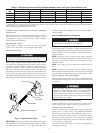
•Back-seating service valves are not equipped with Schrader
valves. Fully back seat (counterclockwise) valve stem before
removing gage-port cap.
•Front-seating service valves are equipped with Schrader
valves.
Federal Regulations require that you do not vent refrigerant to
atmosphere. Recover during system repair or final unit
disposal.
Follow these steps to properly pumpdown a system and avoid
negative suction pressure.
1. Fully back seat (open) liquid- and vapor-tube service valves.
2. Unit is shipped with valve stem(s) front seated (closed) and
caps installed. Replace stem caps after system is opened to
refrigerant flow. Replace caps finger-tight and tighten with
wrench an additional 1/12 turn.
3. Close electrical disconnects to energize system.
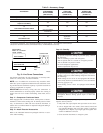
Table 2—Accessory Usage
ACCESSORY
REQUIRED FOR
LOW-AMBIENT
APPLICATIONS
(BELOW 55°F)
REQUIRED FOR
LONG-LINE
APPLICATIONS*
(OVER 50 FT)
REQUIRED FOR
BURIED LINE
APPLICATIONS†
(OVER 3 FT)
Crankcase Heater Yes Yes Yes
Evaporator Freeze Thermostat Yes No No
Accumulator No No Yes
Compressor Start-Assist
Capacitor and Relay
Yes Yes Yes
MotorMaster® Control,
or
Low-Ambient Pressure Switch
Yes No No
Wind Baffle
See low-ambient
Instructions
No No
Unit Risers Recommended No No
Liquid-Line Solenoid Valve
or
Hard-Shutoff TXV
No
See Long-Line
Application
Guideline
Yes
Ball-Bearing Fan Motor Yes‡ No No
* For tubing line sets between 50 and 175 ft, refer to Application Guideline and Service Manual — Air Conditioners and Heat Pumps.
† For buried line applications, refer to Application Guideline and Service Manual — Air Conditioners and Heat Pumps.
‡ Required for low-ambient controller (full-modulation feature) and MotorMaster® Control only.
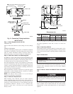
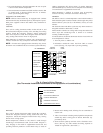
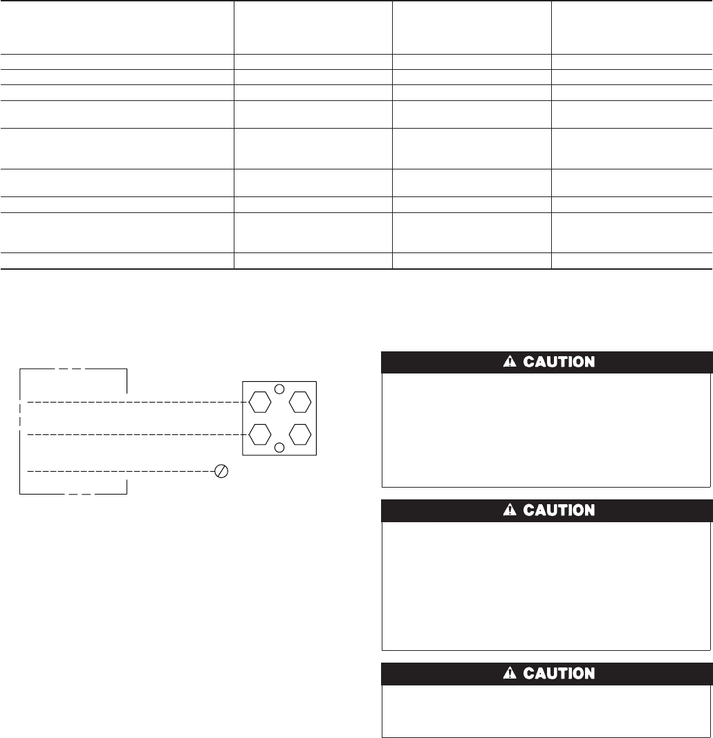
Fig. 8—Line Power Connections
A91056
DISCONNECT
PER N. E. C. AND/OR
LOCAL CODES
CONTACTOR
GROUND
LUG
FIELD GROUND
WIRING
FIELD POWER
WIRING
5