5. Remove crankcase heater from compressor base.
6. Remove compressor holddown bolts and lift compres-
sor off basepan.
7. Remove compressor from unit.
8. Clean system. Add new liquid line filter drier (biflow
type).
9. Install new compressor and position in unit. Connect suc-
tion and discharge lines to compressor. Connect high pres-
sure switch. Ensure that compressor holddown bolts are
in place. Connect wiring. Install crankcase heater.
10. Evacuate and recharge unit.
11. Restore unit power.
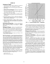
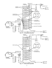
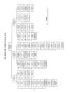
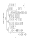
Cooling Mode Operation — See Fig. 16.
1. Hot refrigerant gas from compressor flows through the
reversing valve and is directed to the outdoor coil vapor
header.
2. Once at the outdoor coil vapor header, hot refrigerant gas
flows up to check valve ЉA,Љ which is closed. All refrig-
erant is then directed to complete a path through the lower
6 coil circuits (6 passes in each circuit).
3. Refrigerant flows through from the liquid header side out-
lets into the transfer header, where it flows upward.
4. Refrigerant leaves the transfer header through side con-
nections in 4 locations and enters the middle coil circuits
(4 coil circuits above check valve ЉAЉ).
5. Refrigerant leaves the 4 middle coil circuit and enters the
top portion of vapor header. The refrigerant moves up to
the top 2 remaining coil circuits, where it enters the sub-
cooler section.
6. Subcooled refrigerant leaves the coil circuits through the
side outlets. It passes through check valve ЉBЉ into the
system liquid line and then into the indoor coil.
7. Liquid refrigerant is expanded and evaporated to a low-
pressure vapor in the indoor coil. Refrigerant vapor then
returns to the outdoor unit through the system vapor line,
where it is drawn through the reversing valve and accu-
mulator and back to the compressor suction connection.
Heating Mode Operation — See Fig. 17.
1. Hot gas from compressor flows through the reversing valve
and is directed to the system vapor line and indoor coil
vapor header (not shown). Refrigerant is condensed and
subcooled in the indoor coil and returns to the outdoor
unit through the system liquid line.
2. Check valve ЉBЉ is closed and all liquid refrigerant enters
the liquid header.
3. Refrigerant leaves the liquid header through 12 loca-
tions. It is then expanded in fixed orifice metering de-
vices contained within the outlet tubes.
4. Refrigerant evaporates to low pressure vapor as it com-
pletes its passage through the 12 parallel coil circuits (6
passes each).
5. Refrigerant moves from the coil circuits into the vapor
header, where it is drawn through the reversing valve and
accumulator and back to compressor suction connection.
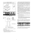
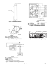
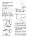
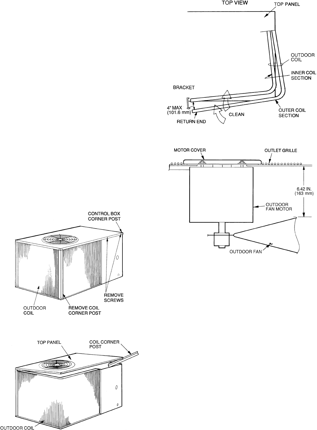
Fig. 12 — Cleaning Outdoor Coil
Fig. 13 — Propping Up Top Panel
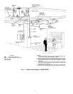
Fig. 14 — Separating Coil Sections
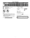
Fig. 15 — Outdoor-Fan Adjustment
12


