


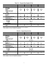
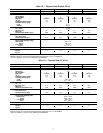
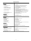
Table 5A — Electrical Data (3 Ph/60 Hz)
UNIT
UNIT COMPR FAN MOTORS (Single Phase)
Model
Volts
MCA ICF
MOCP
(Fuse)
RLA LRA
Total
Fans
FLA (ea)
Fan No.
kW
Nameplate
Supplied*
Min Max 12
38AE012
501 208-230 187 253 62.5 178 100 43.6 170
2
4.3 3.7
1.41
201 380 342 418 35.0 101 50 24.0 93 4.3 3.7
601 460 414 528 29.1 81 40 20.0 77 2.3 1.9
101 575 518 660 22.8 67 35 15.7 62 1.8 1.8
38AE014
501 208-230 187 253 69.3 199 100 49.3 191
2
4.3 3.7
1.41
201 380 342 418 38.0 112 60 26.5 104 4.3 3.7
601 460 414 528 31.7 84 50 22.1 80 2.3 1.9
101 575 518 660 25.6 73 40 17.9 69 1.8 1.8
38AE016
501 208-230 187 253 87.5 274 125 63.6 266
2
4.3 3.7
1.41
201 380 342 418 49.3 153 80 36.0 145 4.3 3.7
601 460 414 528 40.7 124 60 29.3 120 2.3 1.9
101 575 518 660 33.0 100 50 23.8 96 1.8 1.8
38AKS024
501 208-230 187 254 93.4 353 150 67.9 345
2
4.3 3.7
1.41
201 380 342 418 49.7 199 80 34.6 191 4.3 3.7
601 460 414 508 48.1 177 80 34.7 173 2.3 1.9
101 575 518 632 40.1 124 60 28.8 120 1.8 1.8
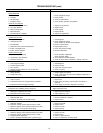
Table 5B — Electrical Data (3 Ph/50 Hz)
UNIT
UNIT COMPR FAN MOTORS 230 v (Single Phase)
Model
Volts
MCA ICF
MOCP
(Fuse)
RLA LRA
Total
Fans
FLA (ea)
Fan No.
kW
Nameplate
Supplied*
Min Max 12
38AE012
803 230 198 264 47.5 134 75 32.9 128
2 2.9 3.5 1.20
903 400 342 457 31.4 80 50 20.0 74
38AE014
803 230 198 264 51.0 149 75 35.7 143
2 2.9 3.5 1.20
903 400 342 457 34.0 89 50 22.1 83
38AE016
803 230 198 264 66.9 206 100 47.9 200
2 2.9 3.5 1.20
903 400 342 457 43.0 121 60 29.3 115
38AKS024
803 230 198 254 91.8 213 150 67.9 207
2 2.9 3.5 1.20303 346 311 380 51.5 121 80 33.3 115
903 400 342 440 50.2 179 80 34.6 173
LEGEND
FLA — Full Load Amps (Fan Motors)
ICF — Maximum Instantaneous Current Flow during start-up (LRAof compressor plus total FLA of fan motors)
kW — Total Fan Motor Input (kilowatts)
LRA — Locked Rotor Amps
MCA — Minimum Circuit Amps per NEC (U.S.A.), Section 430-24
MOCP — Maximum Overcurrent Protection (amps)
RLA — Rated Load Amps (Compressor)
*Units are suitable for use on electrical systems where voltage supplied to the unit terminals is not below or above
the listed limits.
NOTES:
1. The MCA and MOCP values are calculated in accordance with the National Electrical Code (NEC) article 440
(U.S.A. standard).
2. Motor RLA and LRA values are established in accordance with Underwriters’ Laboratories (UL) Standard 1995
(U.S.A. standard).
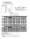
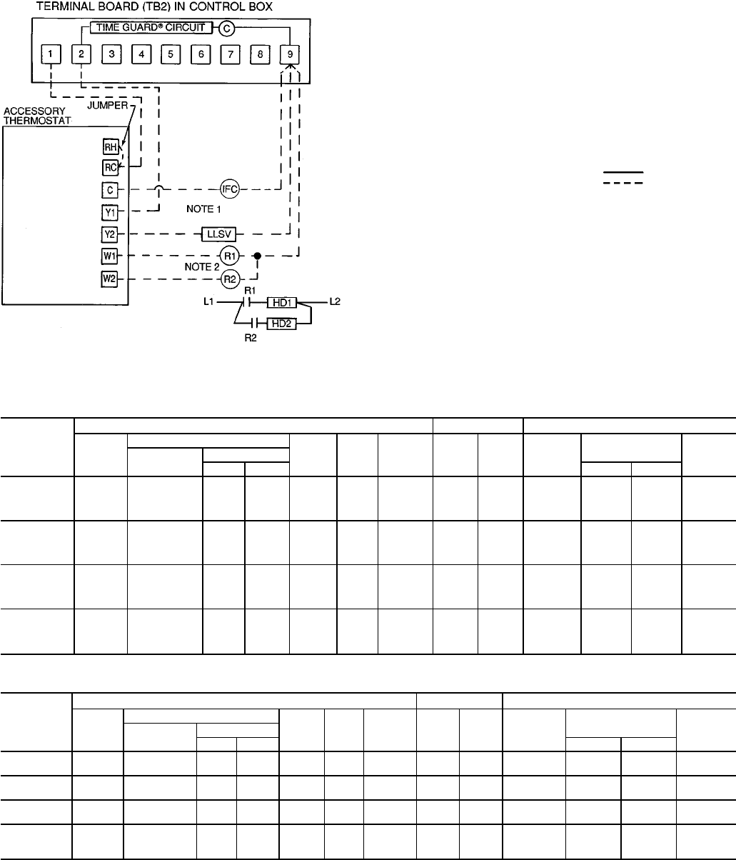
LEGEND
C—Compressor Contactor R—Relay
HD — Heating Device
Factory Wiring
IFC — Indoor-Fan Contactor Field Wiring
LLSV — Liquid Line Solenoid Valve
NOTES:
1. Combination LLSV plus IFC va should not exceed 30 va.
2. Do not exceed 5 va (24 vac) per coil.
3. If va values shown in Notes 1 and 2 must be exceeded, use
accessory relay transformer package 38AE900001.
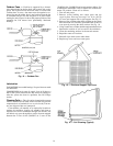
Fig. 7 — Remote Thermostat Wiring
8