


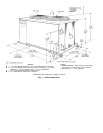
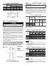
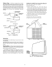
INSTALL FILTER DRIER(S) AND MOISTURE INDICA-
TOR(S) — Every unit should have a filter drier and liquid-
moisture indicator (sightglass). In some applications,depending
on space and convenience requirements, it may be desirable
to install 2 filter driers and sight glasses. One filter drier and
sight glass may be installed at A locations in Fig. 4. Or, 2
filter driers and sight glasses may be installed at B locations.
Select the filter drier for maximum unit capacity and mini-
mum pressure drop. Complete the refrigerant piping from
indoor unit to outdoor unit before opening the liquid and suc-
tion lines at the outdoor unit.
INSTALL LIQUID LINE SOLENOID VALVE — SOLE-
NOID DROP — It is recommended that a solenoid valve be
placed in the main liquid line (see Fig. 4) between condens-
ing unit (38AE/AKS) and fan coil (40RR, 40RE). (A liquid
line solenoid valve is required when the liquid line length
exceeds 100 ft [30.5 m] or when the condensing unit is con-
nected to the chiller barrel in a built-up chiller system.) This
valve prevents refrigerant migration (which causes oil dilu-
tion) to the compressor during the off cycle at low outdoor
ambient temperatures. The solenoid should be wired in par-
allel with the compressor contactor coil. This means of elec-
trical control is referred to as solenoid drop control.
INSTALLLIQUID LINE SOLENOID VALVE (OPTIONAL)
— CAPACITY CONTROL — If 2-step cooling is desired,
place a solenoid valve in the location shown in Fig. 4.
MAKE PIPING CONNECTIONS — Do not remove run-
around loop from suction and liquid line stubs in the com-
pressor compartment until piping connections are ready to
be made. Pass nitrogen or other inert gas through piping while
brazing to prevent formation of copper oxide.
Install field-supplied thermostatic expansion valve(s) in in-
door section. If 2 thermostatic expansion valves are installed
for 2-step cooling, install field-supplied liquid line solenoid
valve ahead of the second expansion valve.
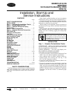
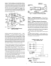
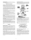
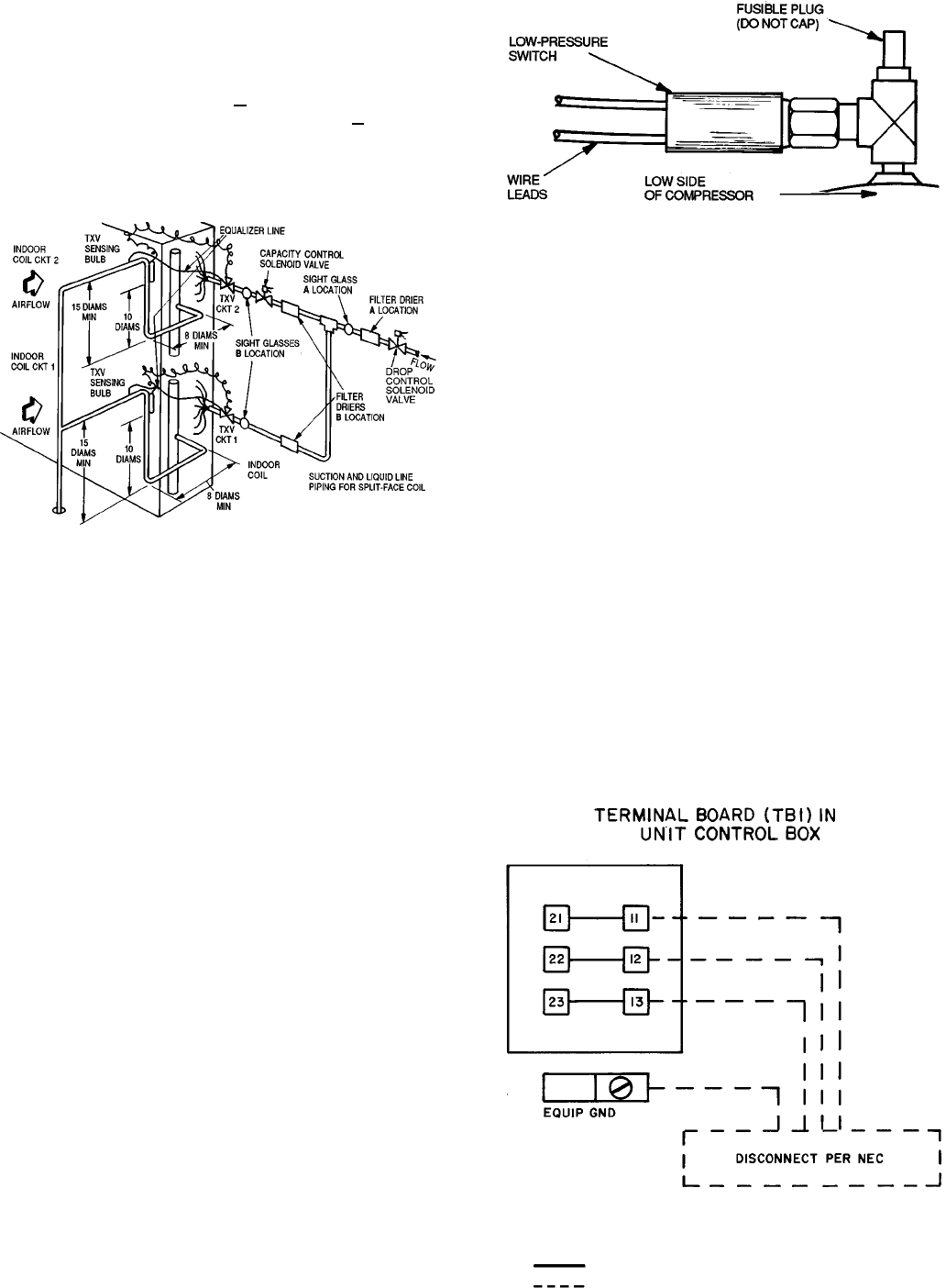
PROVIDE SAFETY RELIEF — A fusible plug is located
on the compressor crankcase or in the liquid line (Fig. 5).
Do not cap this plug. If local code requires additional safety
devices, install them as directed.
Step 4 — Install Accessories — Field install ac-
cessories such as winter start control or low-ambient control
before proceeding with wiring.Refer to the instructions shipped
with the accessory.
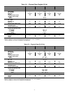
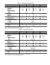
Step 5 — Complete Electrical Connections
POWER WIRING — Unit is factory wired for voltage shown
on nameplate. Provide adequate fuseddisconnect switch within
sight from unit and readily accessible from unit, but out of
the reach of children. Lock switch open (off) to prevent power
from being turned on while unit is being serviced. Discon-
nect switch, fuses, and field wiring must comply with na-
tional and local code requirements. See Tables 5A and 5B.
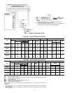
Route power wires through opening in unit end panel to
connection in unit control box as shown on unit label dia-
gram and in Fig. 6. Unit must be grounded.
Affix crankcase heater warning sticker to unit disconnect
switch.
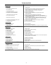
CONTROL CIRCUIT WIRING — Control voltage is 24 v.
See Fig. 7 and unit label diagram for field-supplied wiring
details. Route control wires through opening in unit end panel
to connection in unit control box.
TXV — Thermal Expansion Valve
Fig. 4 — Location of Sight Glass(es)
and Filter Drier(s)
NOTE: 38AKS024 has a fusible plug in the liquid line.
Fig. 5 — Location of Fusible Plug (38AE)
LEGEND
EQUIP GND — Equipment Ground
NEC — National Electrical Code
Factory Wiring
Field Wiring
Fig. 6 — Main Power Supply Wiring
7