


Check Operation — Verify operation of all safety con-
trols. Replace all service panels. Be sure that control panel
cover is closed tightly.
OPERATING SEQUENCE
Cooling —
When the first stage (TC1) of the cooling ther-
mostat closes, the timer starts. After approximately 3 sec-
onds, the timer activates the compressor and fan motor no.
1 contactor. When the liquid pressure builds to approxi-
mately 257 psig (1772 kPa), fan motor no. 2 is energized.
On demand for additional cooling capacity, the second stage
(TC2) of the cooling thermostat closes, energizing a field-
supplied liquid line solenoid (LLS) valve, which opens. This
increases the suction pressure, causing the compressor to op-
erate at higher capacity.
When fan switch is set at AUTO, the indoor-air fan cycles
with the compressor. When the switch is set at CONT, the
indoor-air fan runs continuously.
At shutdown, the Time Guard II timer prevents the com-
pressor from restarting for approximately 5 minutes.
When installed, a field-supplied solenoid valve (wired in
parallel with the compressor contactor coil), shuts off the liq-
uid line to prevent refrigerant migration back to the com-
pressor during the off cycle.
Heating — The heating thermostat (TH) energizes a field-
supplied relay which operates heating controls and ener-
gizes the indoor-fan relay. When the fan switchis set at AUTO,
the indoor-air fan cycles with the heating control. The indoor-
air fan runs continuously when the fan switch is set at CONT.
Fan Cycling — Head pressure control is accomplished
by cycling the fans. The no. 2 fan responds to liquid line
pressure, cycling on at approximately 257 psig (1772 kPa)
and off at approximately 126 psig (869 kPa).
Winter Start Control (If Installed) — When the com-
pressor starts, the control’s bypass timer contacts close for
150 seconds, thereby bypassing the low-pressure switch dur-
ing start-up. After 150 seconds, the bypass timer contacts
open and the low-pressure switch is restored to the safety
circuit.
SERVICE
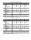
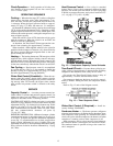
Capacity Control —
A suction pressure-actuated un-
loader controls 2 cylinders and provides capacity control. Un-
loaders are factory set (see Tables 1A-1D), but can be field
adjusted as described in the 2 following sections.
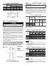
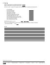
CONTROL SET POINT (cylinder load point) is adjustable
from 0 to 85 psig (586 kPa). To adjust, turn control set point
adjustment nut (Fig. 12) clockwise to its bottom stop. In this
position, set point is 85 psig (586 kPa). Next, turn adjust-
ment counterclockwise to desired control set point. Every
full turn counterclockwise decreases set point by
7.5 psig (51.7 kPa).
PRESSURE DIFFERENTIAL (difference between cylinder
load and unload points) is adjustable from 6 to 22 psig (41.4
to 152 kPa). To adjust, turn pressure differential adjustment
screw (Fig. 12) counterclockwise to its back stop position.
In this position, differential is 6 psig (41.4 kPa). Next, turn
adjustment clockwise to desired pressure differential setting.
Every full turn clockwise increases differential by 1.5 psig
(10.3 kPa).
Head Pressure Control — Fan cycling is a standard
feature. The no. 2 fan cycles in response to changes in liquid
pressure. The switch cycles the fan off at 126 ± 4 psig (869
± 28 kPa) as pressure decreases, and cycles it back on at 257
(+5, −0) psig (1772 [+103, −0] kPa).
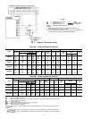
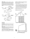
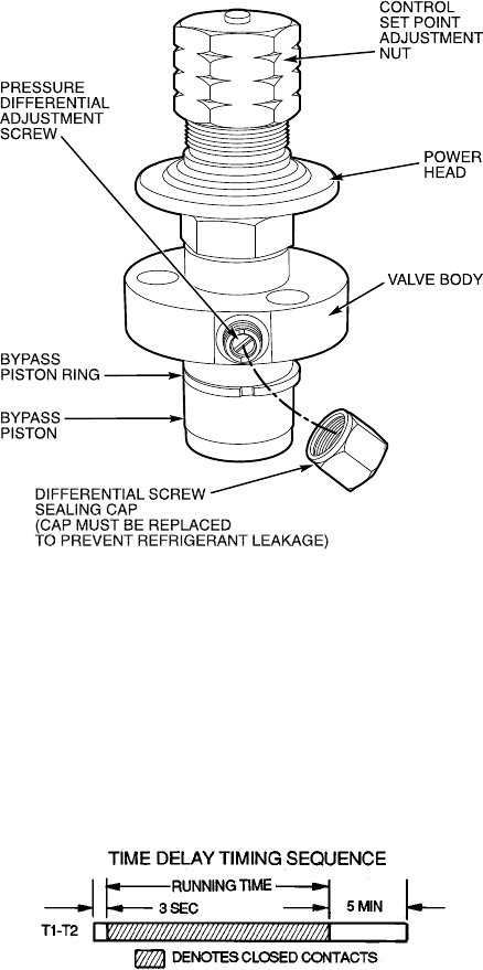
Time Guard II Circuit — Prevents short-cycling by pro-
viding a delay of approximately 5 minutes before restarting
compressor after shutdown from safety device action.
On start-up, the Time Guard II timer causes a delay of
approximately 3 seconds after thermostat closes.
On compressor shutdown, the timer recycles for approxi-
mately 5 minutes. During this time, the compressor cannot
restart.
Refer to Fig. 13 and to label diagram on unit.
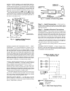
Winter-Start Control (If Required) — Install Ac-
cessory Package 38AE900021.
Crankcase Heater — The heater prevents refrigerant
migration and compressor oil dilution during shutdown when-
ever compressor is not operating. It is wired into the control
circuit, and cycles with the compressor; the heater is off when
compressor is running, and on when compressor is off.
Both compressor service valves must be closed whenever
the crankcase heater is deenergized for more than 6 hours.
The crankcase heater is operable as long as the control cir-
cuit is energized.
Fig. 12 — Compressor Capacity Control Unloader
Fig. 13 — Timer Sequence Chart
13