


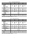
Table2—Weight Distribution
UNIT
WEIGHT — lb (kg)
Total
Operating
Support Point
AB C D
38AE012 732 (333) 142 (65) 138 (63) 225 (102) 227(103)
38AE014 779 (354) 143 (65) 140 (64) 247 (112) 249 (113)
38AE016 789 (359) 143 (65) 143 (65) 250 (114) 253 (115)
38AKS024 900 (408) 178 (81) 168 (76) 269 (122) 285 (129)
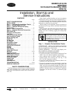
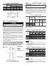
Step 2 — Rig and Mount the Unit
Be sure unit panels are securely in place prior to
rigging.
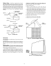
RIGGING — These units are designed for overhead rigging
only. For this purpose, the transverse base channels extend
beyond the sides of the unit, with holes provided in the end
plates to attach cables or hooks. Rig with top skid packaging
assembly in place to prevent unit damage by the rigging cable.
As further protection for the coil faces, plywood sheets can
be placed against the sides of the unit, behind the cables.
Run the cables to a central suspension point so that the angle
from the horizontal is not less than 45 degrees. Raise and set
the unit down carefully.
If it is necessary to roll the unit into position, mount the
unit on longitudinal rails, using a minimum of 3 rollers. Ap-
ply force to the rails, not the unit. If the unit is to be skidded
into position, place it on a large pad and drag it by the pad.
Do not apply any force to the unit.
Raise from above to lift unit from the rails or pad when
unit is in final position.
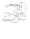
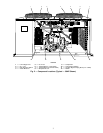
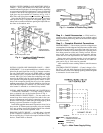
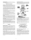
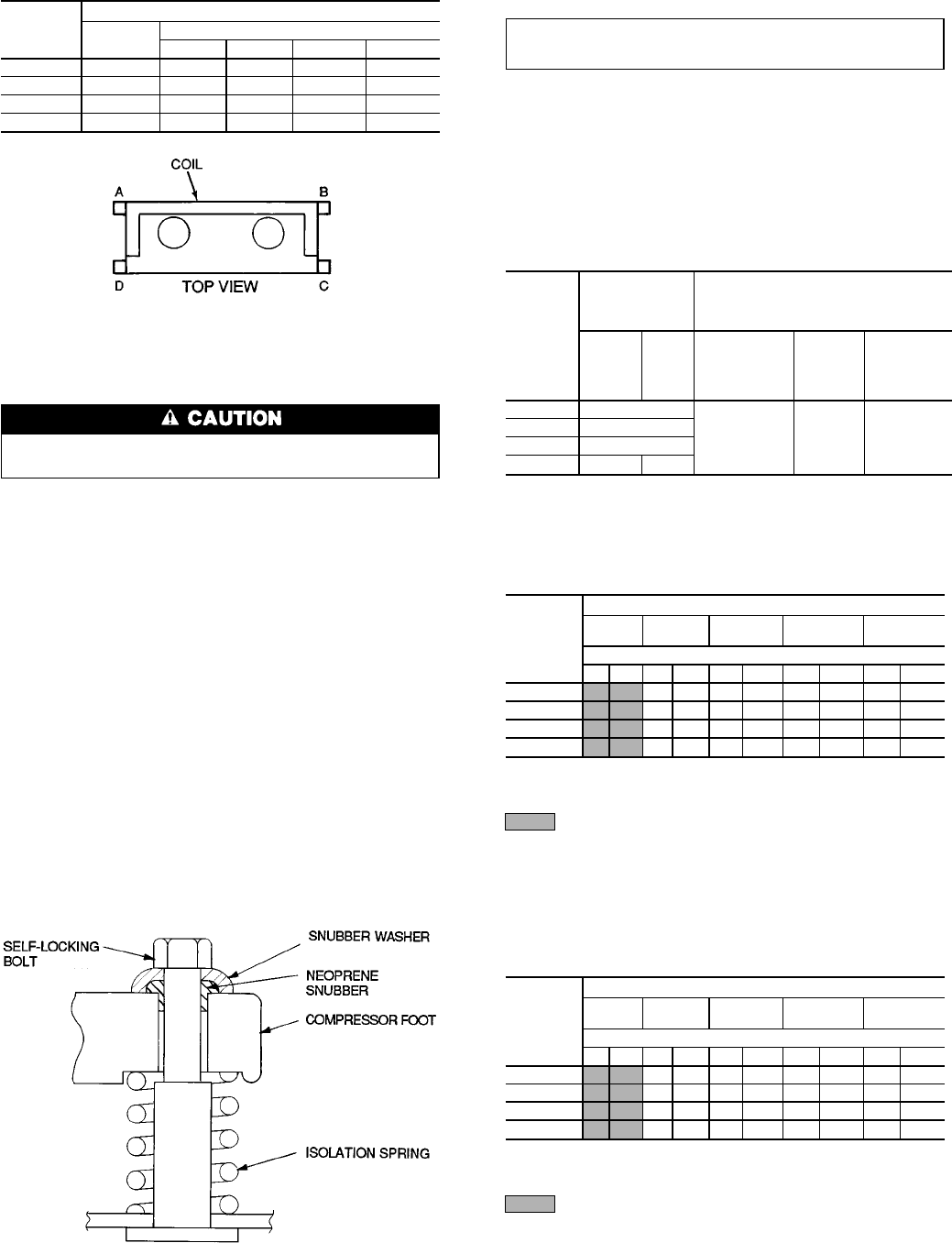
COMPRESSOR MOUNTING — As shipped, the compres-
sor is held tightly in place by self-locking bolts.Before start-
ing unit, loosen self-locking bolts until the snubber
washer can be moved sideways with finger pres-
sure. Do not remove shipping bolts. See Fig. 3.
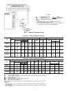
Step 3 — Complete Refrigerant Piping
Connections
IMPORTANT: A refrigerant receiver is not provided
with the unit. Do not install a receiver.
SIZE REFRIGERANT LINES — Consider the length of
piping required between outdoor unit and indoor unit
(evaporator), the amount of liquid lift, and compressor oil
return. See Tables 3, 4A, and 4B and also refer to Part 3 of
Carrier System Design Manual for design details and line
sizing. Refer to indoor installation instructions for addi-
tional information.
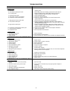
Table 3 — Liquid Line Data
UNIT
MAXIMUM
ALLOWABLE
LIQUID LIFT
ft (m)
LIQUID LINE
60 Hz 50 Hz
Maximum
Allowable
Pressure Drop
psig (kPa)
Maximum
Allowable
Temp.
Loss
F (C)
Filter Drier
and
Sight Glass
Flare Conn.*
in. (mm)
38AE012 52 (15.8)
7 (48.3) 2 (1.1)
5
⁄
8
38AE014 67 (20.4)
38AE016 82 (25)
38AKS024 87 (26.5) 86 (26)
*Inlet and outlet.
NOTE: Data shownis for units operatingat 45 F(7.2 C) saturated suctionand
95 F (35 C) entering air.
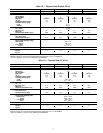
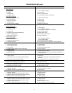
Table 4A — Refrigerant Piping Sizes — 60 Hz
UNIT
LENGTH OF INTERCONNECTING PIPING — FT (M)
0-15
(0-4.6)
15-25
(4.6-7.6)
25-50
(7.6-15.2)
50-75
(15.2-22.9)
75-100
(22.9-30.5)
Line Size — in. OD
LSLSLSLSLS
38AE012
1
⁄
2
1
1
⁄
8
1
⁄
2
1
1
⁄
8
5
⁄
8
1
3
⁄
8
5
⁄
8
1
3
⁄
8
5
⁄
8
1
5
⁄
8
38AE014
1
⁄
2
1
1
⁄
8
1
⁄
2
1
3
⁄
8
5
⁄
8
1
3
⁄
8
5
⁄
8
1
5
⁄
8
7
⁄
8
1
5
⁄
8
38AE016
1
⁄
2
1
3
⁄
8
5
⁄
8
1
3
⁄
8
5
⁄
8
1
5
⁄
8
7
⁄
8
1
5
⁄
8
7
⁄
8
2
1
⁄
8
38AKS024
5
⁄
8
1
5
⁄
8
5
⁄
8
1
5
⁄
8
7
⁄
8
1
5
⁄
8
7
⁄
8
2
1
⁄
8
7
⁄
8
2
1
⁄
8
LEGEND
L—Liquid
S—Suction
Close coupled.
NOTES:
1. Pipe sizes are based ona2F(1.1 C) loss for liquid lines and a 1.5 F
(0.8 C) loss for suction lines.
2. Pipe sizesare based on anequivalent length equal tothe maximum length
ofinterconnectingpiping plus50%forfittings.Amoreaccurateestimatemay
result in smaller sizes.
Table 4B — Refrigerant Piping Sizes — 50 Hz
UNIT
LENGTH OF INTERCONNECTING PIPING — FT (M)
0-15
(0-4.6)
15-25
(4.6-7.6)
25-50
(7.6-15.2)
50-75
(15.2-22.9)
75-100
(22.9-30.5)
Line Size — in. OD
LSLSLSLSLS
38AE012
1
⁄
2
1
1
⁄
8
1
⁄
2
1
1
⁄
8
5
⁄
8
1
1
⁄
8
5
⁄
8
1
3
⁄
8
5
⁄
8
1
3
⁄
8
38AE014
1
⁄
2
1
1
⁄
8
1
⁄
2
1
1
⁄
8
5
⁄
8
1
3
⁄
8
5
⁄
8
1
3
⁄
8
5
⁄
8
1
3
⁄
8
38AE016
1
⁄
2
1
3
⁄
8
5
⁄
8
1
3
⁄
8
5
⁄
8
1
3
⁄
8
5
⁄
8
1
3
⁄
8
5
⁄
8
1
5
⁄
8
38AKS024
5
⁄
8
1
5
⁄
8
5
⁄
8
1
5
⁄
8
5
⁄
8
1
5
⁄
8
7
⁄
8
1
5
⁄
8
7
⁄
8
1
5
⁄
8
LEGEND
L—Liquid
S—Suction
Close coupled.
NOTES:
1. Pipe sizes are based ona2F(1.1 C) loss for liquid lines and a 1.5 F
(0.8 C) loss for suction lines.
2. Pipe sizesare based on anequivalent length equal tothe maximum length
ofinterconnectingpiping plus50%forfittings.Amoreaccurateestimatemay
result in smaller sizes.
Fig. 3 — Compressor Mounting
6