


4
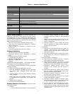
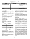
Table 2 — Stand-Alone Transceiver Pin Out
Antenna Installation —
Antennas must be connected
to each transceiver for proper operation. Without an antenna,
two units will not communicate. The higher the gain of the an-
tenna, the longer the range of the transceiver signal. All Carrier
transceivers ship with a 5 db omni-directional 9-in. antenna.
An outdoor antenna is also available from Carrier.
Carrier transceivers are designed to be used only with cer-
tain antenna products. Other higher gain directional antennas
may be purchased through an approved Carrier supplier. Con-
tact Carrier for additional information.
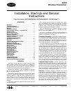
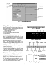
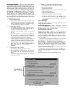
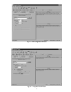
Installation onto a CCN Bus —
Use the RS-232 to
RS-485 converter to install transceivers directly onto an
RS-485 network. An RS-232 to RS-485 converter and power
supply is supplied with each transceiver.
1. Separate the RS-485 converter’s housing with a flat blade
screw driver.
2. Install jumpers in all 5 terminals.
3. Wire the CCN (+) to screw terminal Pin 1, and CCN (-) to
screw terminal Pin 2. See Fig. 2.
4. Cut the power plug off of the power cube 6 in. from the
end.
5. Wire the ground wire of the power supply wire to screw
terminal Pin 5 and the positive (wire with white line) to
screw terminal Pin 6. See Fig 2.
If a transceiver is used to connect directly to a computer, an
RS-232 to RS-485 converter is not required. Only the 9-pin
cable (supplied) is used.
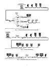
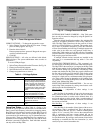
NETWORK TOPOLOGY
The Carrier transceivers support the Broadcast Network
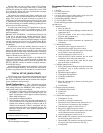
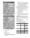
topology. Each transceiver can be configured via its Configura-
tion Manager to work this topology. The transceiver’s Configu-
ration Manager controls how the transceiver transmits and re-
ceives data as connected to the device. (See Fig. 3-5.)
Networks —
Wireless data connectivity applications
require a wide range of networking options. The network
topologies consist of more than two transceivers and may have
a PC to host a network of devices. The PC or network devices
are each physically attached to a transceiver.
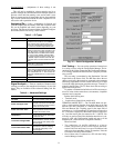
WIRELESS SERVICE TOOL — The wireless Service Tool
setup allows a CCN service technician to install, commission,
and troubleshoot from any location in the building. All CCN
elements on the primary bus are accessible. The wireless con-
nection allows the technician to utilize a laptop computer to
perform all Service Tool functions from anywhere within the
range of wireless communication. If the transceiver is located
on a rooftop, it is possible to gain wireless access to the build-
ing from several miles away.
NOTE: Wireless buss extensions on CCN systems with sec-
ondary buses are recommended for temporary use only. Per-
manent use is NOT recommended.
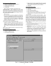
WIRELESS BUS EXTENSION — The wireless bus exten-
sion setup allows a bus to be extended to a remote location
through the use of the wireless transceivers. This set up can be
used to connect two portions of a CCN bus when physical wir-
ing cannot be used or is not cost effective. This set up may also
be used to connect controllers in two different buildings by
placing the transceiver on the roofs of the buildings. This set up
is not recommended for CCN systems that contain secondary
buses.
PIN NAME I/O FUNCTION
1
DCD — Data Carrier Detect Output Session Status (True)
2
TxD — Transmit Data Output Data from transceiver to the attached device
3
RxD — Receive Data Input Data into transceiver from the attached device
4
DTR — Data Terminal Ready Input Data/Command Mode
5
Gnd — Signal Ground
6
DSR — Data Set Ready Output Always Asserted (High)
7
RTS — Request to Send Input HW Flow Control (internally pulled up)
8
CTS — Clear to Send Output HW Flow Control (default: asserted/High)
9
RI — Ring Indicate Output Status Change (default: de-asserted/Low)
Wireless communication signals can be adversely affected
by physical and/or electrical interference. Carrier wireless
transceivers should NOT be installed in applications where
temporary loss of communications cannot be tolerated by
the control system. Suitable applications include equipment
monitoring, alarm monitoring, control overrides and tem-
porary service connections.
1
2
3
5
4
6
7
8
9
10
x
x
x
x
x
CCN (+)
V (+)
V (GND)
RED
CCN (-)
BLACK
LEGEND
NOTES:
1. Install end of line termination jumpers between 1 and 2, 3 and
4 if unit is used with the RS-485 network.
2. Install jumpers between 5 and 6, 7 and 8, 9 and 10 to use the
converter in a CCN 2 wire set up.
Fig. 2 — Converter Detail
CCN —
Carrier Comfort Network
GND —
Ground (-)