


14
TROUBLESHOOTING (See Table 7)
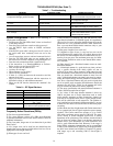
Table 7 — Troubleshooting
System Configuration —
Refer to the following to
check system configuration:
• Do the power and link LEDs blink 3 times as described
in the Setup section?
• Does the power indicator remain on after power up?
• Are the RS232 9-pin cables or RS485 converters
attached?
• If the RS232 9-pin cable is being used, do all 9 wires in
the serial cable have continuity from one end to the
other?
• Are all connections secure to unit and connected device?
• Does the TX LED blink when you are sending data to
the transceiver from the computer or originating device?
• Does the unit communicate with a loopback test?
• If the transceiver is a Broadcast/Remote or Point-to-
Point, are the sync and power LED's on?
• How far apart are the transceivers?
• Are they out of range?
• What antennas are you using?
• Where are they mounted?
• If there is a cable run between the transceiver and the
antenna, how long?
• Have you tried to communicate with the transceiver in
different locations or with different antennas?
• What are the RF barriers between the antennas? See
Table 8.
Table 8 — RF Signal Barriers
Frequently Asked Questions (FAQs)
Q: Can I use an external antenna?
A: Yes, many different versions of 2.4 GHz omni-directional
or directional antennas can be used. Please contact Carrier for
additional information.
Q: Can I use other, longer runs of coax than what is provided
from Carrier?
A: Yes. Longer coax can be used but one should keep the
length of the coax as short as possible and use low loss coax as
appropriate for the length of the run.
Q: What types of coax can I use?
A: RG-316, RG-223, LMR240, 300, 400, 600 and many other
types that are suitable for 2.4 GHz RF signals. It is important to
choose a low loss coax and realize that the longer the coax the
greater the loss. Also, remember that the Carrier transceivers
have a reverse thread SMA female connectors only so your
coax will need to mate with that.
Q: How great a length of coax can I use?
A: It depends on type of coax. A very low loss coax can be
used at distances up to roughly 50 ft. It is critical, however, that
the correct coax and connectors are used and that the coax sys-
tem loss is not too great. The maximum power out of a Stand-
Alone Carrier Transceiver at the reverse thread SMA connec-
tor is 500 mW.
Q: When should I use a directional antenna versus an omni-
directional antenna?
A: A directional antenna is a good choice any time you have
only a specific direction from which signals are sent or
received. If you have a Host (master) Carrier transceiver and
there are Remote Carrier transceivers in all directions from the
Host you should use a directional antenna in most if not all
cases. A directional antenna can extend your range by concen-
trating the radiated energy from the antenna in a certain direc-
tion. Also, a directional antenna will only receive signals that
are in its specific angle reception. RF interference outside the
antennas area will not be ‘visible’ by the antenna and in this
way can increase the transceivers receive capability.
Q: The range specification with omni-directional antennas is
2 miles. Does that require line-of-sight?
A: Yes it does. If the range between antennas is short, say
1000 ft and there are no major obstructions such as earth,
major metallic structures or other obstructions, chances are
good that an acceptable RSSI (receive signal strength indica-
tion) will be achievable at each transceiver. The problem is,
every applications environment is different and there is no way
to know for sure unless one tests the units in that actual physi-
cal setting.
Q: How much does line-of-sight matter with Carrier transceivers?
A: As a general rule, line-of-sight is required to assure commu-
nications. The Carrier transceivers operate at 2.4 to 2.4835
GHz with a maximum power output of 500 mW. The trans-
ceiver’s ability to receive adequate signal levels is entirely
dependent on the placement of the antennas and the distance
they are from one another. There is no absolute guarantee in
advance that a given installation of Carrier transceivers will
yield a good communication link. However, if the range is
under 1000 ft, adequate communication can be accomplished
in many cases without line-of-sight as long as the proper anten-
nas have been selected and installed as required. In general,
with ranges up to and exceeding 1500 ft, line-of-sight is
required.
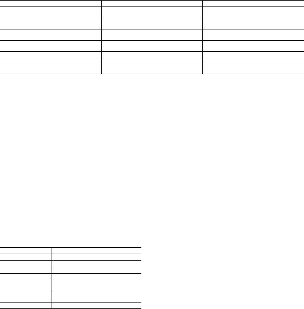
PROBLEM POSSIBLE CAUSE POSSIBLE SOLUTION
“Timeout?” messages are displayed in the
Configuration Manager general tab fields.
The equipment is not connected properly. Check that all connections are secure.
Make sure transceiver has power (LED 1 is lit).
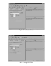
Wrong serial port is selected. Select the correct serial port in the serial tab of
the Configuration Manager
Antenna cannot be threaded onto the antenna
connector.
Antenna and antenna connector have “left-
handed” threads.
Turn antenna connector counterclockwise to
attach to transceiver.
LED 1 not lit Power is not being supplied to unit. Check power supply connection into unit and
outlet. Make sure supply of power is active.
LED 1 and LED 2 flash 3 times Normal operation. No need to troubleshoot.
Open the Configuration Manager and get an
error message
Outdated DLL. Run 401COMUPD.exe included in program
disk to install COMCTL32.DLL in your
C:\Windows\System directory.
BARRIER SEVERITY
Concrete Wall High
Metal Wall High
Wood Framed Wall Moderate
Glass Low
Trees Low to High depending on type
(high = Pine)
People High
(mount antenna above pedestrian traffic)
Vehicular Traffic High