


3
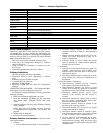
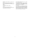
Table 1 — Hardware Specifications
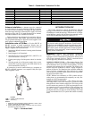
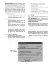
Serial Communications —
In order to configure any
transceiver, a 9-pin RS-232 cable must be used. This is neces-
sary because Pin 4 is used to transmit the configuration data
into EEPROM and other pins are used during the configuration
process as well (see Table 2). A 9-pin RS-232 cable is included
with all stand-alone transceivers.
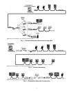
The 9-wire cable must be used in the following cases:
• when using the Configuration Manager to initialize/
setup a transceiver
• when a Carrier CCN Interface is connected via the
RS-232 port
• when field upgrading the transceiver software
Software Installation
The software has the following requirements:
• Windows® 95/98 or above (depending on software
used)
• Pentium processor 233 MHz or higher
• 1 available RS-232 serial port
• Minimum 32 MB DRAM
• Maximum 20 MB hard disk space for Configuration
Manager
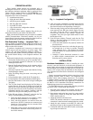
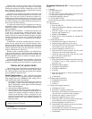
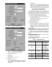
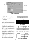
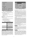
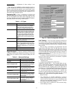
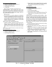
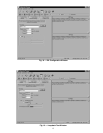
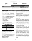
CONFIGURATION MANAGER — The Configuration Man-
ager program is used to configure all transceivers.
To install the Configuration Manager software, perform the
following procedure:
1. Make sure all Windows applications are closed.
2. Insert the Installation CD-ROM into the appropriate
drive. Select folder “CONFIG_111300” then select
“Disk 1”.
3. Open the contents of the drive using Windows Explorer
or My Computer.
NOTE: Take note of all warnings and notes that refer
to computer/software requirements when running this
program.
4. Double-click on “Setup.exe.”
5. Follow the on-screen instructions.
Antenna Selection and Location —
Several factors
effect signal strength:
1. Location
a. Line of sight between antennas is always preferred.
b. Locations directly adjacent to walls or other
structures should be avoided for omni-directional
antennas.
c. Barriers between antennas should always be con-
sidered (see barrier information on page 16 for
degree of penetration).
d. Antennas should be moved within the desired
space to determine if a better location within the
desired area can be found.
2. Polarization
a. Antennas must be oriented in the same plane. For
example, omni-directional stick antennas must
both be vertical in the same plane in order for reli-
able signal reception.
b. Directional antennas must be oriented in the same
plane utilizing the vertical pole identification on
the antenna.
3. Omni-directional vs. Directional
a. Omni-directional antennas provide essentially
equal signal strength around the antenna.
b. Omni-directional antennas can receive a signal
coming from virtually any direction in relation to
the antenna as long as polarization is not a factor.
c. Directional antennas provide greater signal
strength in the direction that the antenna is
oriented.
d. Directional antennas are labeled with a vertical
pole for proper orientation with both omni-
directional and directional antennas.
e. Directional antennas should be pointed in the
direction of the receiving antenna.
f. Directional antennas will not receive any signals
coming from behind the antenna.
g. Directional antennas should be rotated to deter-
mine if bouncing the wireless signal can be utilized
in order to achieve wireless communications.
h. For best results it is recommended that a direc-
tional antenna be used in conjunction with an
omni-directional antenna. With this setup signal
strength is improved while antenna lineup is fairly
straightforward.
Frequency
2.400-2.4835 GHz license-free ISM band in U.S. (varies in other countries where transceivers have been certified)
Radio Type
Frequency Hopping Spread Spectrum
Number of Channels
417 independent, non-interfering frequencies
Data Rate
600 bps to 9.6 kbps full duplex
Transmit Power Output
10mW to 500mW nominal, self-adjusting (lower maximum power output where required)
Indoor Range
Up to 1,500 feet (457 m) in normal construction
Outdoor Range
Up to 2 miles (3.2 km) with omni-directional antenna.
Up to 12 miles (19.3 km) with optional directional antenna (line of sight to the horizon)
Protocol
CSMA (Carrier Sense Multiple Access)
Flow Control
Supports Hardware, Software or None
Error Detection &
Correction
CRC 16 error detection; forward error correction can correct errors in 1 out of every 4 bits transmitted
Certification
FCC Part 15 Certified, Industry Canada, Japan, Europe, Brazil.
Other International certifications pending
Electrical Interface
RS-232C Voltage Levels
Physical Interface
Standard RS-232C DB-9 (female) connector
Input Power
Shipped with a 115VAC power adapter providing: Voltage: > 6.5 V and < 9.0 V Ripple: Less than 250mV (RMS) from DC to
1MHz
Input Current Draw
Idle: 200mA Transmit: 550mA instantaneous current Transmit/Receive (time averaged over 100msec): 360mA
Environmental Temperature
Range
–4 F to +140 F, –20 C to +60 C
Humidity
0% to 95% (non-condensing)
Physical Dimensions
1.2 inches height (30mm) x 3.8 inches width (97mm) x 5.2 inches length (132mm)
Weight
6 ounces (170 grams)