


3
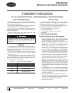
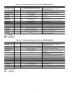
Table 2C — Contents of Accessory Kit, Part No. 00EFN900002900A
LEGEND
PART NUMBER QUANTITY DESCRIPTION USAGE
00PSN500175200A 2
Tube assembly including solenoid valve,
ball valve, and 90 degree bend tube assembly
One per circuit (Circuit A and B for 30XA325, 350,
circuit A and C for 30XA450, 500). Cooler shell
minimum load port, connect to 30GX5034892 adapter.
30GX5034892 2 1 in. - 14 ORS x
1
/
2
in. NPT adapter One per circuit. Cooler shell minimum load port.
00PPG000011600A 2 Solenoid coil assembly
One per circuit. Plug onto solenoid valve stub
on 00PSN500171700A tube assembly.
KA66AA062 4 5/8 in. tube clamp
Secure minimum load piping to the frame
as required.
DE40BA705 21
1
/
8
in. x 1
1
/
8
in. x
5
/
8
in. Tee
One per circuit. Discharge manifold on the side
of condenser coil V.
TH70400410 2Cable assembly
One per circuit. Connect to solenoid coil
assembly and terminal block TB5 in control box.
00PPN500000401A 4 No. 10 screw Mount tube clamps
32GB500432E 1 HGBP/Pump board Mount in control box
TH70400864 1 Harness assembly Wiring between TB5 and HGBP/Pump board
HH83ZB001 1 24V circuit breaker (CB14) Mount on display bracket in control box
A6X10004352 4 No. 8 screw Mount HGBP/Pump board
A6X10004434 4 Board mounting standoff
Mount HGBP/Pump board (325,350,450,500:
all voltages)
TH70400852 1 Communication cable assembly 30XA325,350,450,500: all voltages.
HY89TB010 3 Wire nut Splice communication cable
HGBP — Hot Gas Bypass
ORS — O-Ring Seal
TB — Terminal Block
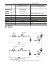
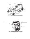
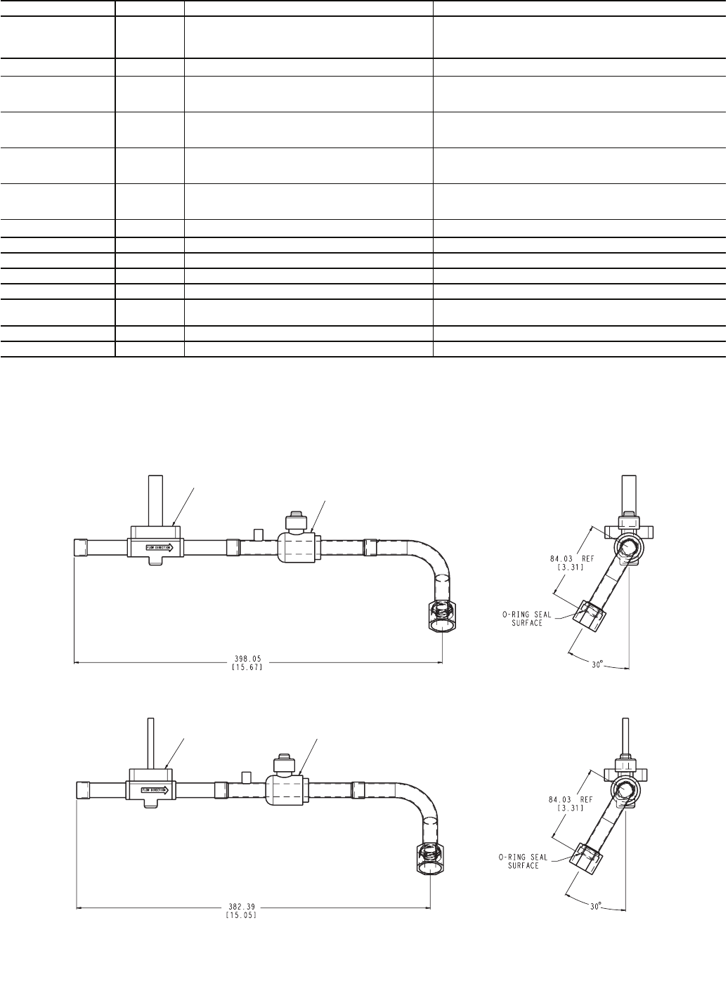
BALL VALVE
SOLENOID VALVE
TUBE ASSEMBLY 00PSN500175200A
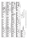
SOLENOID VALVE
BALL VALVE
TUBE ASSEMBLY 00PSN500171700AA
NOTE: Dimensions are in mm [in.].
Fig. 1 — Dimensions of Tube Assemblies Provided in Accessory Kit
a30-4499
a30-4500