


6
Install HGBP/Pump Board and Control Wiring
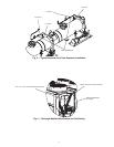
1. Attach the solenoid coil assembly to the solenoid valve
plunger on the tube assembly for each circuit. One cable
assembly TH70400410 is supplied per circuit. Secure the
DIN connector end on the solenoid valve coil with the
screw in the connector. Verify the square rubber gasket is
in place to ensure connection remains watertight.
2. Route the other end of the cable to the main control panel
(where the display is located). For the circuit A solenoid,
connect leads to TB5-7 and TB5-13. For the B circuit
solenoid, connect leads to TB5-8 and TB5-13. For the C
circuit solenoid (30XA400-500 only), connect the leads
to TB5-6 and TB5-13. In all cases, the black wire from
the solenoid must be connected to TB5-13 to ensure
correct polarity.
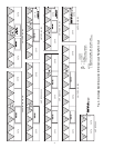
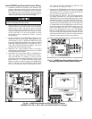
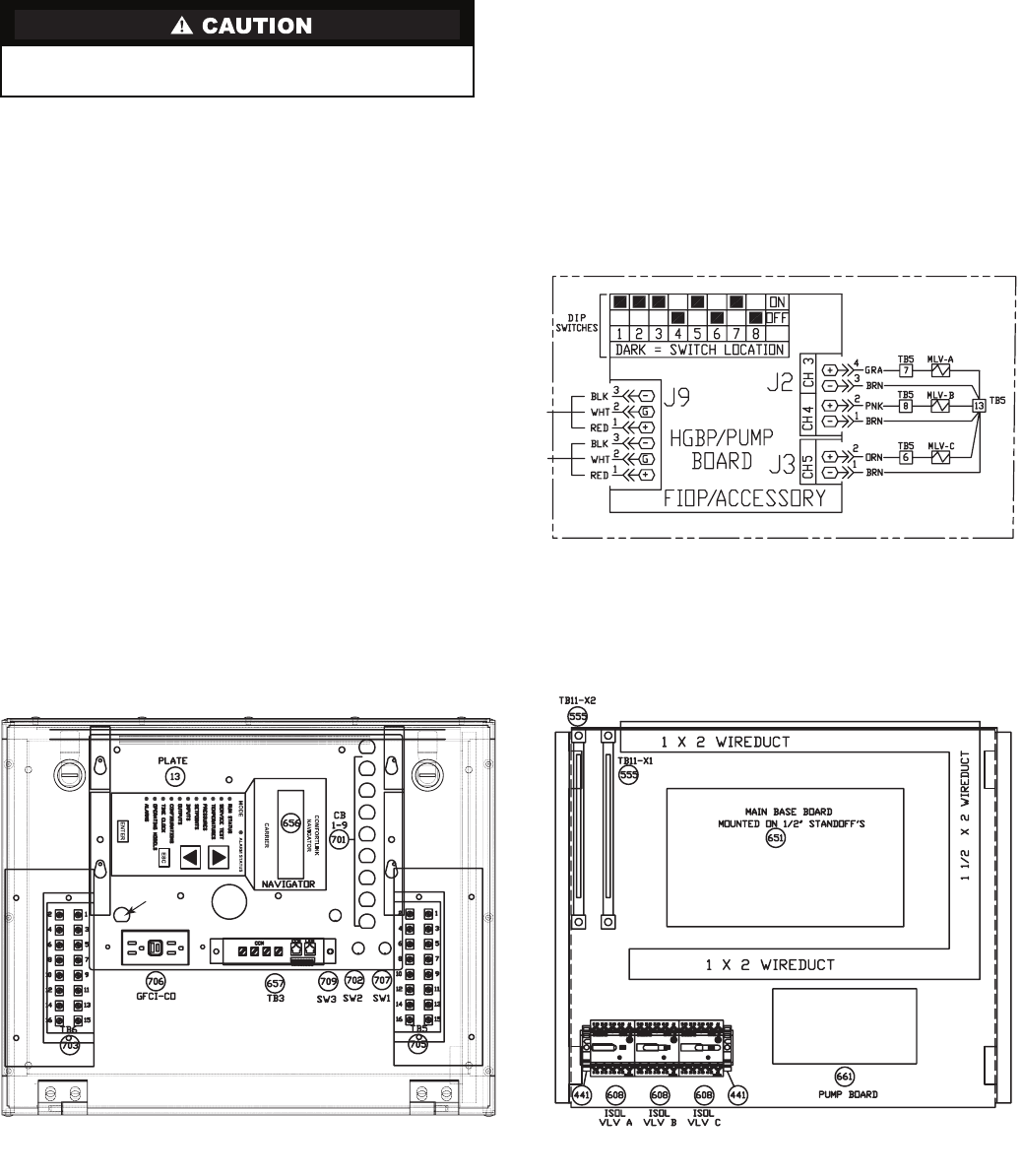
3. Set the board address of the HGBP/Pump Board by posi-
tioning the dual in-line package (DIP) switches to the
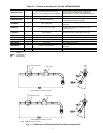
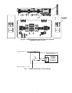
correct settings. See Fig. 5. Mount the HGBP/Pump board
in the main control panel with the No. 8 screws provided
(mounting standoffs required for 30XA080-120: 200 v,
230 v, 380 v and 30XA140-500: all voltages). See Fig. 6A
and 6B for the board mounting location.
4. Mount the 24-v circuit breaker (CB14) in the CB14
mounting hole on the display bracket. See Fig. 6A and 6B
for the mounting hole location.
5. Connect the 24-v power from TB10-X1 (30XA080-120:
460 v, 575 v only) or TB11-X1 (30XA080-120: 200/230 v
and 30XA140-500: all voltages) to CB14 with the
provided red wire in the harness assembly. Find two 2-pin
plugs marked J1-11,12 with red and brown wires in the
harness assembly. Connect the plug to the HGBP/Pump
board J1 with the red wire connected to CB14 and the
brown wire connected to TB10-X2 (30XA080-120: 460 v,
575 v only) or TB11-X2 (30XA080-120: 200/230 v and
30XA140-500: all voltages). See Fig. 7.
6. Using harness TH70400864 provided in the kit, connect
TB5 pins 6 (30XA400-500 only), 7, 8, and 13 to HGBP/
Pump board J2 CH3, CH4 and J3 CH5 (30XA400-500
only). Use the pins inside TB5. See Fig. 5.
7. For 30XA080-120: 200/230 v, 380 v and 30XA140-500:
all voltages, disconnect the 3 pin plug on MBB J9B (or
EMM board J9A) for communication and plug it in to the
HGBP/Pump board J9. Use the additional communica-
tion cable assembly TH70400852 provided in the kit to
connect between HGBP/Pump board J9 and MBB J9B
(or EMM board J9A when EMM board exists). The com-
munication cable in the TH70400864 harness will not be
used. For 30XA080-120: 460 v, 575 v, connect the 3 pin
plug of the communication cable in the TH70400864
harness to the HGBP/Pump board J9 and splice the other
end of the cable to the communication network using the
wire nuts provided in the kit. Be sure to splice the wires
with same color together to ensure correct polarity.
Take care connecting leads to terminal blocks. Incorrect
polarity will damage the control boards.
a30-4503
Fig. 5 — HGBP/Pump Board Address Switch and
Wiring for Minimum Load Solenoid Output
HGBP/PUMP
BOARD
CB14
Fig. 6A — HGBP/Pump Board and CB14 Mounting Location
(30XA080-120: 200 v, 230 v, 380 v and 30XA140-500: all voltages)
a30-4504