


Manufacturer reserves the right to discontinue, or change at any time, specifications or designs without notice and without incurring obligations.
Catalog No. 04-53300010-01 Printed in U.S.A. Form 30XA-6SI Pg 1 12-06 Replaces: New
Book 2
Ta b 5 c
Installation Instructions
Part No: 00EFN900002700A, 00EFN900002800A, 00EFN900002900A
SAFETY CONSIDERATIONS
Installing, starting up, and servicing air-conditioning equip-
ment can be hazardous due to system pressures, electrical com-
ponents, and equipment location.
Only trained, qualified installers and service technicians
should install, start up, and service this equipment.
When working on air-conditioning equipment, observe
precautions in the literature and on tags, stickers, and labels at-
tached to the equipment.
Follow all safety codes. Wear safety glasses and work
gloves. Use care in handling equipment.
GENERAL
This control accessory reduces 30XA chiller capacities be-
low the standard lowest capacity step. This capacity reduction
provides more precise control of leaving fluid temperature
during light load conditions.
The minimum load control solenoid valve limits the amount
of gas that can be bypassed from the condenser without
impacting oil return.
One accessory package is required for 30XA080-350 units.
Two accessory packages are required for 30XA400-500 units
to accommodate connections for three refrigerant circuits. See
Table 1 for accessory package usage.
Table 1 — Accessory Package Usage
INSTALLATION
Examine the package contents for correct part numbers. If
any of the components are damaged, file a claim with the
shipping company and notify your Carrier representative.
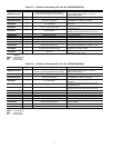
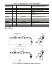
See Table 2A, 2B, or 2C for package contents. See Fig. 1 for
dimensional drawings of tubes included in the kit.
The following material is field supplied:
•
5
/
8
in. OD copper tubing
•
5
/
8
in. OD copper tube elbows and couplings
(as required)
• Loctite 554 thread sealing compound
• Parker Super O-lube O-ring lubricant
Install the Solenoid Valve Tube Assembly
1. Remove refrigerant charge from the circuits using an
approved refrigerant recovery device before proceeding
with this installation. Follow good piping practices.
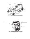
2. Locate the discharge manifold for minimum load
piping on the side of the coil V for each circuit as
shown in Fig. 2. Locate the
1
/
2
in. NPT pipe plugs on
the top of the cooler for each circuit. See Fig. 3.
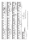
3. Remove the
1
/
2
in. NPT pipe plugs from the top of the
cooler. Use the thread sealing compound and install
one 1 in.-14 O-ring seal (ORS) x
1
/
2
in. NPT adapter
for each circuit. Lightly lubricate each O-ring with
O-lube and attach the tube assembly to each adapter.
See Fig. 3. Be sure to attach the correct tube assembly
to the cooler. Refer to the usage column in Tables 2A,
2B, and 2C for tube assembly part number correspond-
ing to the unit size and circuit. The nut on the tube
assembly should be torqued to 30 ft-lb (40 N-m).
4. Remove the trim panel on the discharge manifold for
minimum load piping on the side of the coil V. Use a
tubing cutter to cut 1
1
/
2
in. out from the discharge mani-
fold for each circuit. See Fig. 4. Braze a tee in between
the gap and, depending on the routing of the hot gas
bypass tubing, have the tee’s remaining port facing either
left or right.
5. Use field-supplied
5
/
8
in. OD copper tubing and fittings
(as required) to pipe from the solenoid valve outlet to the
5
/
8
in. port of the tee on the discharge manifold. Use the
provided
5
/
8
in. tubing clamps to secure the tubing to the
unit frame as necessary.
6. When piping is completed, leak test the assembly.
7. Evacuate, dehydrate, and recharge each circuit. Be sure to
use the correct type and amount of refrigerant listed in the
nameplate data and base unit documentation.
8. Restore power to the unit.
Be sure power to equipment is shut off before performing
maintenance or service to avoid electrocution. Lock out
and safety-tag all disconnects. There may be more than one
disconnect.
30XA UNIT SIZE ACCESSORY PART NO.
080-240 00EFN9000002700A
260-300 00EFN9000002800A
325, 350 00EFN9000002900A
400
00EFN9000002700A,
00EFN9000002800A
450, 500
00EFN9000002800A,
00EFN9000002900A
30XA080-500
Minimum Load Control Accessory