


Step 5 — Configure Unit for Minimum Load Con-
trol —
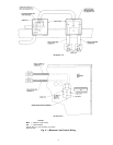
Once the piping installation and wiring installation
are complete, the chiller must be configured for minimum
load control operation. This may be done using the unit key-
pad (HSIO-2). Set the LOCAL/OFF switch in the OFF
position.
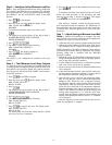
1. Press on the keypad.
2. Press the down arrow until the display reads:
MIN. LOAD VALVE SELECT
DISABLE
3. To enable the minimum load valve feature, press
.
4. The display may read as follows. (If not, skip to Step 7.)
PASSWORD PROTECTED FUNCTION
ENTER PASSWORD
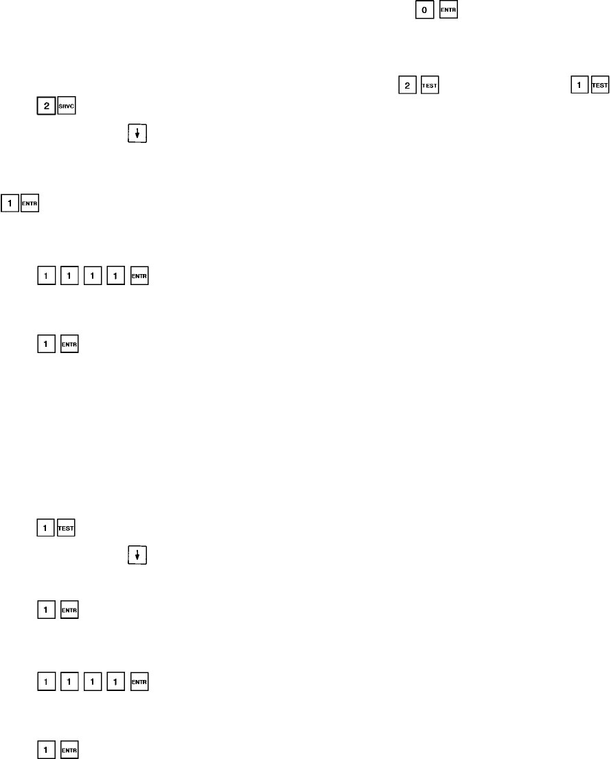
5. Press .
6. The HSIO-2 again displays the following:
MIN. LOAD VALVE SELECT
DISABLE
7. Press . The display changes to:
MIN. LOAD VALVE SELECT
ENABLE
The chiller is now configured for minimum load valve
control.
Step6—TestMinimum Load Relay Outputs
—
After the accessory components are installed and the unit
is recharged and reconfigured, test the operation of the relay
and solenoid valve using the Quick Test software function.
Test Circuit A as follows (the LOCAL/OFF switch must be
in the OFF position):
1. Press on the HSIO-2 keypad.
2. Press the down arrow until the display reads:
MIN. LOAD VALVE A
RELAY IS OFF
3. Press .
4. The display may read as follows. (If not, skip to Step 7.)
PASSWORD PROTECTED FUNCTION
ENTER PASSWORD
5. Press .
6. The HSIO-2 again displays the following:
MIN. LOAD VALVE A
RELAY IS OFF
7. Press to energize the relay. The display reads:
MIN. LOAD VALVE A
RELAY IS ON
An audible click will be heard. Verify that the solenoid
valve for Circuit A is energized.
8. Press to turn off the minimum load valve relay
for Circuit A.
To check the operation of the solenoid valve on Circuit B,
follow the same procedure as the preceding, but enter
enter in Step 1, instead of . The display
screens will be for Circuit B instead of A.
After testing is complete, recheck all electrical connec-
tions for proper location and tightness. For 30HX units, re-
place and secure the access panels for the unit control box.
For 30GX units, secure the junction box covers to the junc-
tion boxes.
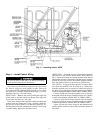
Step 7 — Adjust Setting of Minimum Load Ball
Valve —
Before the installation is complete, the mini-
mum load ball valve must be adjusted to suit the application.
Calibrate one circuit at a time as follows:
1. Adjust the ball valve so that it is approximately half open.
2. Operate the chiller in Manual Control mode, with one cir-
cuit operating, and all compressor loaders deenergized.
NOTE: Operation of the chiller in Manual Control mode is
described in the Controls, Start-Up, Operation, and Trouble-
shooting Guide that is included with the 30GX,HX
Ecologic™ chillers.
3. Record the cooler ⌬T (the difference between cooler en-
tering fluid temperature and cooler leaving fluid tempera-
ture) at this fully unloaded condition.
4. Use the Manual Control feature to enable the minimum
load valve for the circuit that is operating.
5. Observe and record the cooler⌬T with the minimum load
valve energized.
6. Adjust the minimum load ball valve until the cooler tem-
perature difference reading from Step 5 is equal to half of
the temperature difference reading from Step 3.
7. Open the ball valve to decrease the temperature differ-
ence or close the ball valve to increase the temperature
difference (⌬T). When the valve is adjusted correctly,
the difference between cooler entering and leaving fluid
temperatures when the minimum load control is ener-
gized must be at least half of the temperature difference
when the minimum load control is deenergized. For ex-
ample, if the difference between the cooler entering and
leaving water temperature is 3° F with the valve deen-
ergized, then the difference between cooler entering and
leaving water temperature must be at least 1.5° F with the
valve energized.
Once the outputs have been tested and the ball valve ad-
justed, the installation is complete.
6