


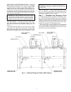
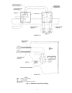


INSTALL BALLAND SOLENOIDVALVES — Using good
piping practice, braze ball valve and solenoid valve into
5
⁄
8
-in. minimum load piping. Fig. 2 shows a typical 30HX
installation and Fig. 3 shows a typical 30GX installation, in-
cluding valve locations and orientation. Ensure that ball valve
is fully open, and that both the ball and solenoid valve are
protected from excess heat during brazing process. Wrap wet
cloths around valve bodies during brazing to prevent dam-
age to the valves from heat.
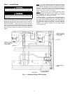
IMPORTANT: When installing solenoid valve, make
sure that flow direction arrow on valve body points
towards the cooler. The minimum load control will not
function correctly if this valve is installed backwards.
CONNECT PIPING — Check the ends of the tubes where
they will be inserted into the Swagelok fittings. To avoid
leaks, tube ends must be round and free of burrs, nicks, and
grooves.
Insert tube ends into fittings as far as they will go. When
tube bottoms out, tighten the compression nut finger-tight
while holding the fitting body. Use backup wrench to hold
fitting body and tighten compression nut another 1
1
⁄
4
turns.
IMPORTANT: Do NOT overtighten the fittings. Over-
tightening the fittings can deform the tube ends and
cause leaks.
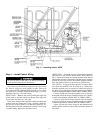
30GX UNITS ONLY — Using good brazing practice, braze
the
5
⁄
8
-in. minimum load tubing to the copper nipple on the
discharge line (minimum load port) between the condenser
coil and oil separator. See Fig. 1 and 3.
Step 3 — Dehydrate and Recharge Circuit
—
When piping has been completed, leak test the assem-
bly. If one of the Swagelok fittings leaks, slowly tighten the
compression nut until the leak stops. If this does not fix the
leak, the connection must be reinstalled using a new ferrule
and backup ring in the fitting. Contact your Carrier repre-
sentative for assistance in locating these parts.
After leak testing, evacuate, dehydrate, and recharge the
circuit using an approved refrigerant recovery device. Cor-
rect type and amount of refrigerant are listed on unit name-
plate and in base unit documentation.
Fig. 2 — Installing Fittings and Valves, 30HX (Typical)
3