


3
INSTALLATION IN 38AKS014-024/INDOOR
FAN COIL (CONSTANT VOLUME)
SPLIT SYSTEM COMBINATION
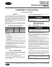
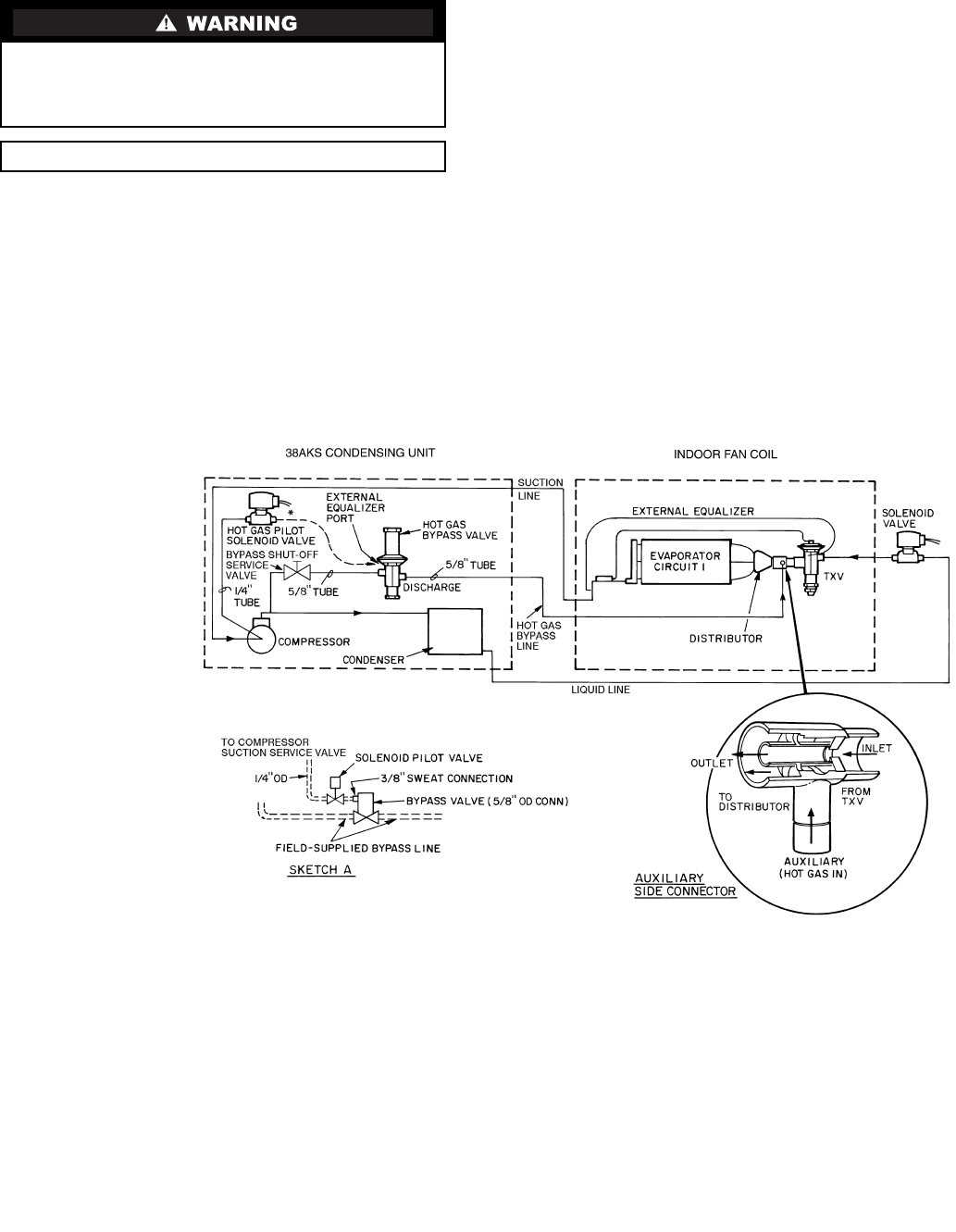
Step 1 — Install Piping (See Fig. 4)
1. In applications where the air handler refrigerant distribu-
tor is not equipped with a side outlet connection, it is rec-
ommended that a Sporlan in-line auxiliary side connector
with standard distributor be used. Refer to the installation
instructions for the indoor fan coil to obtain nozzle size
and distributor connection size. Select the auxiliary side
connector based on this information. The side connector
must be installed on refrigerant circuit no. 1 (first stage of
cooling) of the fan coil being used.
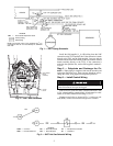
2. Install a field-supplied
1
/
4
in. NPT to
1
/
4
in. flare fitting on
the gage connection port of the compressor suction
service valve.
3. Sweat the pilot solenoid valve supplied in the hot gas ac-
cessory package directly to the hot gas bypass valve on
the
3
/
8
in. ODF external equalizer port.
4. Install field-supplied
1
/
4
in. copper tube (flared with a nut
on each end) between the compressor suction valve and
the hot gas pilot solenoid valve.
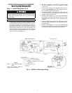
5. Connect a field-supplied
5
/
8
in. OD copper tube between
the discharge line process tube (hot gas stub) and a field-
supplied manual shutoff service valve, avoiding any traps
in piping.
6. Connect another field-supplied
5
/
8
in. OD copper tube be-
tween the manual shutoff valve outlet and the hot gas by-
pass valve inlet.
7. Connect a field-supplied
5
/
8
in. OD copper tube between
the leaving side ofthehot gasbypassvalveand theSporlan
auxiliary side connector (distributor-side connector).
Shut off all power to the unit and remove refrigerant charge
using an approved refrigerant recovery device before pro-
ceeding with installation. Failure to do so may result for
personal injury.
IMPORTANT: Do not bury refrigerant piping underground.
LEGEND
*Pilot valve connects directly to
bypass valve per sketch A.
TXV — Thermostatic Expansion
Valve
Fig. 4 — 38AKS Hot Gas Bypass Piping