


2
Install the field-supplied
1
/
4
in. OD tubing from the SAE
connection to the TXV equalizer line. If the connection is made
directly to the TXV, use the field-supplied, 3-way tee with an
internal branch (install horizontally in the line with the internal
branch attaching directly to the TXV). If the connection is
made into the equalizer line, use the field-supplied, standard 3-
way tee.
Step 2 — Dehydrate and Recharge the Cir-
cuit —
When piping is completed, leak test the assembly and
replace the filter drier cores. Then evacuate, dehydrate, and re-
charge the circuit, using approved refrigeration practices.
Step 3 — Install Control Wiring
Follow all local codes and NEC (National Electrical Code,
U.S.A.) when installing control wiring. All wire must be a min-
imum of 16 AWG (American Wire Gage, U.S.A.).
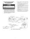
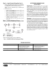
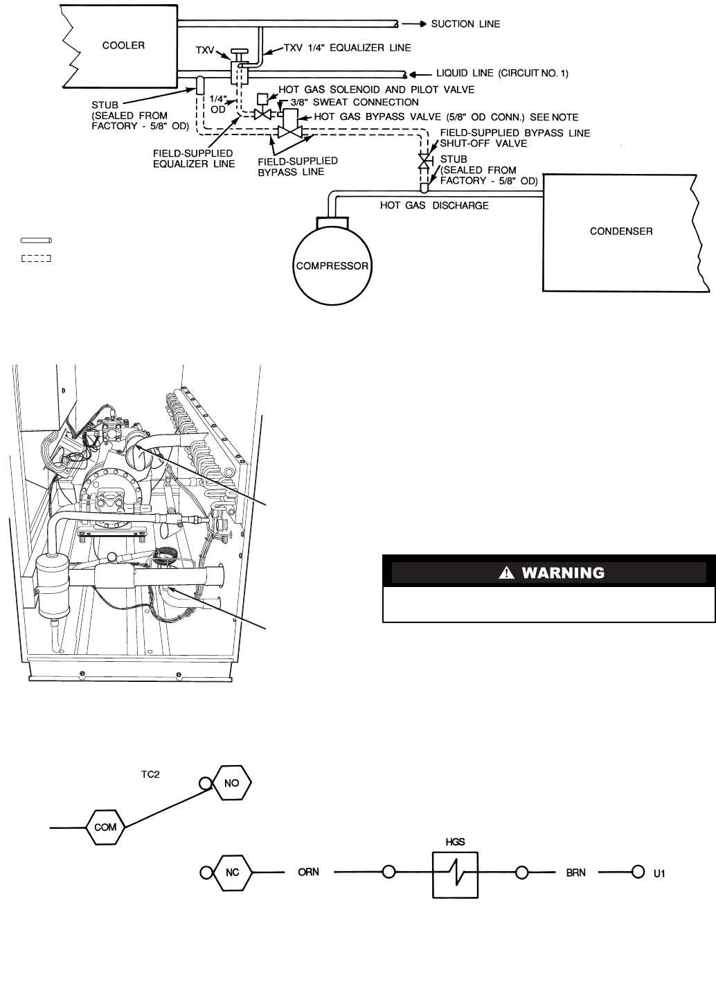
Connect control wires as shown in Fig. 3. At hot gas sole-
noid (HGS), connect to brown and orange wires as shown.
Be sure all power to the unit is off before proceeding, and
that all disconnects are open and tagged.
LEGEND
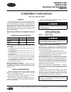
NOTE: The bypass valve in this package has
5
/
8
in.
connections and can be used directly on 30GT015-
035 units.
TXV — Thermostatic Expansion Valve
Factory Piping
Field Piping
Fig. 1 — 30GT Piping Schematic
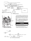
DISCHARGE
STUB
(HIDDEN)
LIQUID
STUB
Fig. 2 — 30GT Stub Locations
Fig. 3 — 30GT Hot Gas Solenoid Wiring
LEGEND
COM — Common NC — Normally Closed TC — Temperature Controller
HGS — Hot Gas Solenoid NO — Normally Open U1 — Unloader 1