


.-
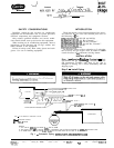
UNITS 30HK,HLO15-060 and
$?TO%-035
(See Fig. 1.)
Bvnass
Line
-
Connect the field-supplied line to the
factory-provided stubs in the discharge line
*fro-m
the
circuit no. 1 compressor and in the circurt no.
1
hquld
line,
between expansion valve and cooler (stubs are sealed
from factory).
Bypass Valve
-
Install the valve in the
bypass
line as
close to the cooler as possible. This
mimmrzes
liquid
storage between valve and cooler when valve is closed
and prevents flood of liquid refrigerant when the valve
opens. To ensure proper closing, install the bypass valve
in a horizontal section of the bypass line, with the pilot
valve installed vertically (coil on top).
Solenoid Pilot Valve
-
Install on the bypass valve at the
external equalizer
@/&in.
OD sweat connection). The
outlet side of the pilot valve is a l/4-in. SAE thread. Run
a l/4-in. OD tube from this connection to the thermo-
static expansion valve (TXV) equalizer line, If the
connection is made directly to the TXV, use a
l/4-in.
FL
x l/4-in. female flare tee. If the connection is made into
the equalizer line, use a standard l/4-in. FL tee.
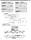
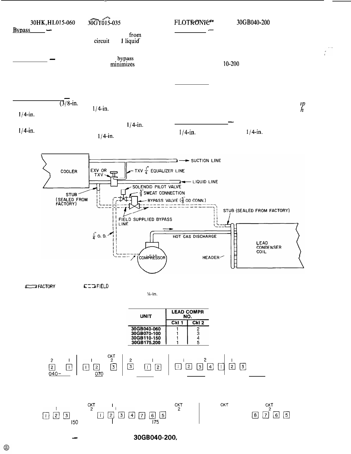
FLOTLWWW” UNITS,
30GB040-200
(See Fig. 2.)
Bypass Line
-
Install field-supplied line between the
header on inlet side of lead coil and the entrance to the
cooler. Two factory-sealed stubs are provided in each
circuit, one on the lead coil header and one on the liquid
line between the Flotronic expansion valve (EXV) and
the cooler.
NOTE: The 30GB 1 lo-200 units have 2 stubs in the high
side of each circuit, one on each lead coil header; it is
necessary to connect piping to only one of these stubs.
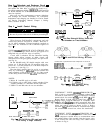
Bvpass Valve
-
Install the valve in the bypass line as
close to the cooler as possible. This minimizes liquid
storage between the valve and cooler when valve is
closed and prevents flood of liquid refrigerant when the
valve opens. To ensure proper closing, install the by ass
valve in a horizontal section of the bypass line, wit
R
the
pilot valve installed vertically (coil on top).
Solenoid Pilot Valve
-
Install on the bypass valve at
the external equalizer. The outlet side of the pilot valve is
a l/4-in. SAE thread. Run a l/4-in. OD tube from this
connection to the suction valve of the lead compressor
in the circuit.
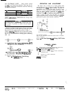
SUCTION LINE VALVE
EXV- ELECTRONIC EXPANSION VALVE
TXV- THERMOSTATIC EXPANSION VALVE
-FACTORY
PIPING
E=ZaFIELD
PIPING
NOTE: Circuit 2 should be piped same as circuit 1. The %-in, tube should be connected to the lead compressor in both circuits.
CKT CKT CKT
TiT
CKT CKT CKT CKT CKT CKT
b
b
p&J
pJ
$J
p-&
&j
&g
m
b
pJ
q 2pJ
040-
060
070 075,080
090,100 110,125
CKT
TT
CKT
TT
CKT
YT
&o
q
ma
pJ&-JpJ
j-?JpJa
q l2Jlml-g
IxJTJmB
150 175 200
Compressor numbers, viewed facing compressor side of unit.
Fig. 2
-
Schematic Piping; 3OGBO40-200, with Electronic Controls (Flotronic)
2