


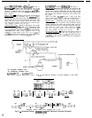
ALL FLOTRONIC UNITS
-
Units require control
relays
tained
!
R) and Time Delay Module. They may be ob-
rom your Carrier distributor under the following
Carrier Part Numbers:
Rl and R2
R3
Time Delay Module
115-v
23Cbv
24-v
HN61KK041 DPDT
HN61KK913 DPDT
HN61 KK040
DPDT
30HK501602
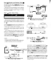
UNITS 30HK,HL015 THROUGH
060 (Except 020,
60 Hz, and 0 15, 50 Hz.)
IMPORTANT: On 30HK,HL 2-compressor units,
the SEQUENCE switch on the control panel must
be in the l-2 position to obtain hot gas bypass
operation.
Run the conduit from the bypass valve to one of the
knockouts provided on the right side of the unit control
box. Connect the control wires as shown in Fig. 7.
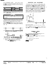
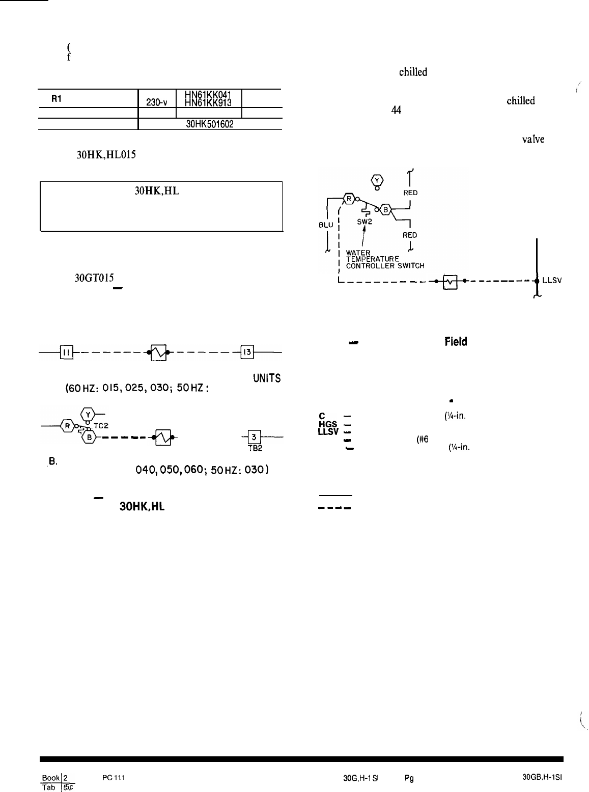
UNITS
30GTO15
THROUGH 035 (except 020, 60 Hz,
and 015, 50 Hz)
-
Connect control wires as shown in
Fig. 8. At LLSV, connect to existing splice containing
white wire.
-j+------+g+----+J-
TB2
HGS
TB2
A. CONNECTIONS FOR SINGLE-COMPRESSOR UNITS
(60~~:
015,025,030;
50~z:
020,025)
-me--
------
-El--
HGS
TB2
,B.
CONNECTIONS FOR TWO-COMPRESSOR UNITS
(50 AND 60HZ:
040,050,060;
50HZ:
0301
See Combined Legend.
Fig. 7
-
Hot Gas Bypass Field Wiring;
30HK,HL Units
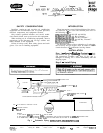
OPERATION AND ADJUSTMENT
The bypass valve is factory set to begin opening when
suction pressure drops to about 62 psig. This pressure
corresponds to a chllled water controller set point of
approximately 44 F. If the chilled water set point is lower
than 44 F, it will be necessary to decrease the bypass valve
y;
setting for proper operation. Conversely, for
chllled
water
set points above
44
F, the bypass valve setting must be
increased. A change in condensing temperature will also
require a change in bypass valve set point. As condensing
temperature decreases, decrease the bypass
vaIve
set
point until it opens at the desired conditions.
i,--------
--e---t-
i
LLSV
HGS
See Combined Legend.
Refer to unit wiring label inside front access door for complete
wiring schematic.
Fig. 8
-
Hot Gas Bypass
Fierd
Wiring; 30GT Units
FiGS
1
LLSV
-
TB
-
TC2
-
cl
0
----
COMBINED LEGEND
(Fig. 3 - 8)
Compressor Contactor
(%-in.
Female Quick-Conn)
Hot Gas Bypass Solenoid (Splice Conn)
Liquid Line Solenoid Valve
Terminal Block
(#6
Ring Conn)
Temperature Controller (X-in. Female Quick-Conn)
Terminal on TB
Terminal on Control Component
Factory Wiring
Field Wiring
Manufacturer reserves the right to discontinue, or change at any time, specifications or designs without notice and without incurring obligations.
Book 2
-+
PC171
Catalog No. 533-039
Printed in U.S.A. Form 30G,H-1
S1
PC4
4
2-89 Replaces: 30GB,WlSI
Tab 5c