


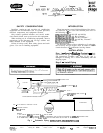
Step 3
-
Dehydrate and Recharge Circuit
-
When
piping has been completed, leak test the assembly
and replace the filter drier, or core(s) for circuit no. 1.
On single-compressor chillers (30HK,HLO 15,025 and 030
for 60 Hz, 020,025 for 50 Hz; 30GT) the filter drier itself
must be replaced.
After core (or drier) replacement, evacuate, dehydrate
and recharge the circuit. Procedures for evacuation,
dehydration and charging are detailed in Carrier Stand-
ard Service Techniques Manual, Chapter 1, Refrig-
erants, Sections 6 and 7.
Step 4
-
Install Control Wiring
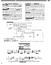
TIME DELAY
MODULE
600K
RESISTOR
HGS
4x”r,ct-4-
RI R2
TIME DELAY
MODULE
I
Be sure all power to the unit is off before proceeding.
1
Wires between field-installed components and unit
control box must be enclosed in conduit. Wire size is
no. 16 AWG minimum. Wire-end terminals required on
field wires are indicated in the Combined Legend for
Fig. 3
-
8.
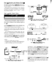
UNITS 30GB040 THROUGH 070 FLOTRONIC (See
Fig. 3.)
-
Control logic allows the hot gas bypass to be
energized only on the first stage of capacity.
A unit with 2 unloaders has the automatic lead/lag
feature which allows starting of either circuit, and
thus must have 2 hot gas bypass packages, one per circuit
(see Fig. 4).
On the 040-060 units, R3 should energize with com-
pressor no. 2. On the 070 unit. R3 energizes with com-
pressor no. 3. In both instances, it is the lead compressor
on circuit no. 2 (see Fig. 5.)
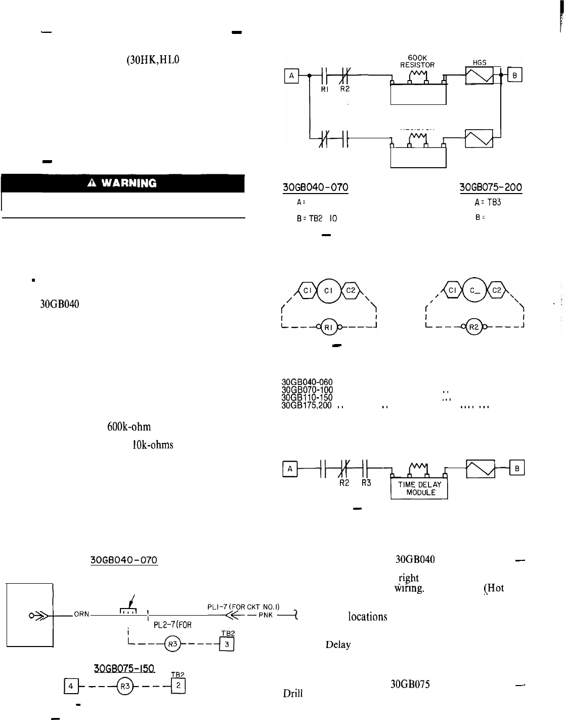
The time delay module must be set for a one-minute
delay by connecting a 600k-ohm resistor between the
center terminals of the module (see Fig. 6). (One second
of time delay results from each lOk-ohms of resistance.)
NOTES:
1. Relays R 1 and R2 apply to all units.
2. R3 applies only to units with a single unloader. Units
with no unloaders or 2 unloaders do not require R3.
3. 30GB 175 and 200 units do not use unloaders.
30G6040-070
RELAY
BOARD
J6
4--
FIELD SPLICE
e
ORN
r4
,
I
,
PLI-‘(YR
CKTF”,;.‘)
PIN 4
I
PL2-7(FOR CKT NO.21
30GB075-150
TB4 TE2
r--a--+J
NOTE: 3063175,200
-
R3 DOES NOT APPLY.
Fig. 3
-
R3 Coil Wiring (R3 used only with
units having a single unloader)
3OGB040-070 3066075-200
~
A= TB2 4
cl
AzTB3
I
cl
B=TB2
IO
q
6:
TB2 2
cl
I
Fig. 4
-
Hot Gas Solenoid Wiring, Units with
No Unloaders or Two Unloaders
Fig. 5
-
RI and R2 Coil Wiring, All Units
Connect R2 in parallel with lead compressor in circuit 2:
30GB040-060
. . . . . . . . . . . . . . . . . . . . . . . . . . . . . . . . . . . . . . . Comp 2
30GB070-100
. . . . . . . . . . . . . . . . . , . . . . . . . . . . *. . . . . . . . . . Comp 3
30GBliO-150
. . . . . . . . . . . . . . . . . . . . . . . . . . . .
I
+.
. . . . . . . . Comp 4
30GB175,200 .
.,
. . . . . . . , .
.,
. . . . . . . . . . . . . . . . .
,.
*. .
.,.
Comp 5
(Refer to Fig. 2 for compressor locations.)
iwt
RI R2 R3
Fig. 6
-
Hot
Gas Solenoid Wiring,
Single
Unloader Units
600K
RESISTOR
HGS
ell
FLOTRONIC’” UNITS, 30GB040 THROUGH 070
-
Drill a hole to accommodate a standard conduit fitting
in bottom of control box at fight end, adjacent to existing
entrance hole for control wiring. Locate HGR
(,Hot
Gas
Bypass Relay) in right side of control box adjacent to
existing relays. Using the HGR base as a template, mark
mountmg hole locations and drill appropriate hole. Run
conduit from the bypass valve to the control box and wire
relays into control circuit as shown in Fig. 4. Relays
and Time DeIay Module should be installed in the upper
left corner of the control box, above the transformer.
FLOTRONIC UNITS, 30GB075 THROUGH 200
-
Driil 2 holes in the bottom right of the control box, next
to the compressor conduit holes, to accommodate stand-
ard conduit fittings. Run conduit from the bypass valve
to the control box and wire relays into control circuit
as shown in Fig. 4.