


3
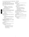
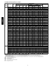
PHYSICAL DATA
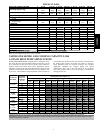
UNIT SIZE---SERIES, VOLTAGE 18---30 24---30 30---30 36---30 42---30 48---30 60---30
Operating Weight lb (kg)
207
(93.9)
204
(92.5)
211
(95.7)
252
(114.3)
239
(108.4)
314
(142.4)
361
(163.8)
Shipping Weight lb (kg)
218
(98.9)
236
(107.1)
222
(100.7)
287
(130.2)
250
(113.4)
348
(157.9)
395
(179.2)
Compressor Type Scroll
REFRIGERANT Freon (R --- 22)
Control TXV (R --- 2 2 Hard Shuto ff)
Charge lb (kg)
7
(3.2)
7
(3.2)
6.8
(3.1)
8.1
(3.7)
9.5
(4.3)
13.5
(6.1)
16.5
(7.5)
COND FAN
Air Discharge Vertical
Air Qty (CFM) 2233 2614 3167 3334 3334 4046 4046
Motor HP 1/12 1/10 1/5 1/8 1/8 1/4 1/4
Motor RPM 800 800 800 800 800 800 800
COND COIL
Face Area (Sq ft) 19.4 21.56 19.40 25.15 17.60 25.15 30.18
Fins per In. 20 20 20 20 20 20 20
Rows 1 1 1 1 2 2 2
Circuits 5 6 6 6 8 8 11
VALVE CONNECT. (In.) ID
Vapor 5/8” 5/8” 3/4” 3/4” 7/8” 7/8” 7/8”
Liquid 3/8”
REFRIGERANT TUBES* (in.)OD
Vapor (0---80 Ft Tube Length) 5/8” 5/8” 3/4” 3/4” 7/8” 7/8” 1 --- 1/ 8
Liquid (0---80 Ft Tube Length) 3/8”
* For tubing sets between 80 and 200 ft. horizontal or 20 ft. vertical differential, consult the Longline Guideline.
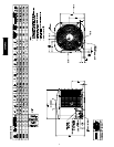
Note: See unit Installation Instruction for proper installation.
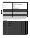
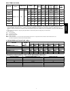
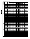
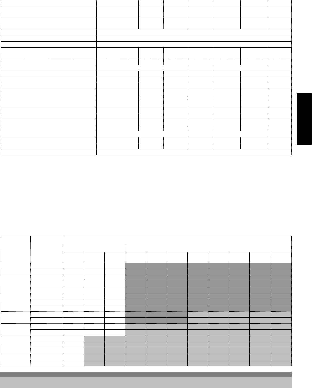
VAPOR L INE SIZ I NG AND COOLING CAPACITY LOSS
1--STAGE HEAT PUMP APPLICATIONS
LONG LINE APPLICATION: An application is considered ”Long
line” when the total equivalent tubing length exceeds 80 ft. (24.38
m) or when there is more than 20 ft. (6.09 m) vertical separation
between indoor and outdoor units. These applications require
additional accessories and system modifications for reliable system
operation. The maximum allowable total equivalent length is 250
ft. (76.2 m). The maximum vertical separation is 200 ft. (60.96 m)
when outdoor unit is above indoor unit, and 60 ft. (18.29 m) when
the outdoor unit is below the indoor unit. Refer to Accessory
Usage Guideline below for required accessories. See Longline
Application Guideline for required piping and system
modifications. Also, refer to the table below for the acceptable
vapor tube diameters based on the total length to minimize the
cooling capacity loss.
Unit Nominal
Size (Btuh)
Acceptable
Vapor Line
Diameters
(In.) OD
Cooling Capacity Loss (%)
Total Equivalent Line Length ft. (m)
Standard Application Long Line Application Requires Accessories
25
(7.62)
50
(15.24)
80
(24.38)
80+
(24.38+)
100
(30.48)
125
(38.10)
150
(45.72)
175
(53.34)
200
(60.96)
225
(68.58)
250
(76.2)
18,000
R --- 22 HP
5/8 0 1 1 1 2 3 3 4 5 5 6
3/4 0 0 0 0 0 1 1 1 1 2 2
24,000
R --- 22 HP
5/8 0 1 3 3 3 5 6 7 8 9 10
3/4 0 0 0 0 1 1 1 2 2 3 3
7/8 0 0 0 0 0 0 0 0 1 1 1
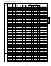
30,000
R --- 22 HP
5/8 1 3 5 5 6 8 10 11 13 15 17
3/4 0 1 1 1 2 3 3 4 5 5 6
7/8 0 0 0 0 1 1 1 2 2 2 3
36,000
R --- 22 HP
3/4 0 1 2 2 3 4 5 6 7 8 9
7/8 0 0 1 1 1 2 2 3 3 4 4
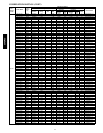
42,000
R --- 22 HP
3/4 1 2 3 3 4 5 7 8 9 10 11
7/8 0 1 1 1 2 2 3 4 4 5 5
48,000
R --- 22 HP
3/4 1 2 4 4 5 7 8 10 11 13 14
7/8 0 1 2 2 2 3 4 5 5 6 7
1 --- 1/8 0 0 0 0 0 0 1 1 1 1 1
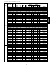
60,000
R --- 22 HP
7/8 1 2 3 3 4 5 7 8 9 10 11
1 --- 1/8 0 0 1 1 1 1 2 2 2 3 3
Standard Length = 80 ft. (24.38 m) or less total equivalent length
Applications in this area are long line. Accessories are required as shown recommended on Long Line Application Guidelines
Applications in this area may have height restrictions that limit allowable total equivalent length, when outdoor unit is below indoor unit See
Long Line Application Guidelines
25HCR3C